GPIO Usage Guidelines
How to Use
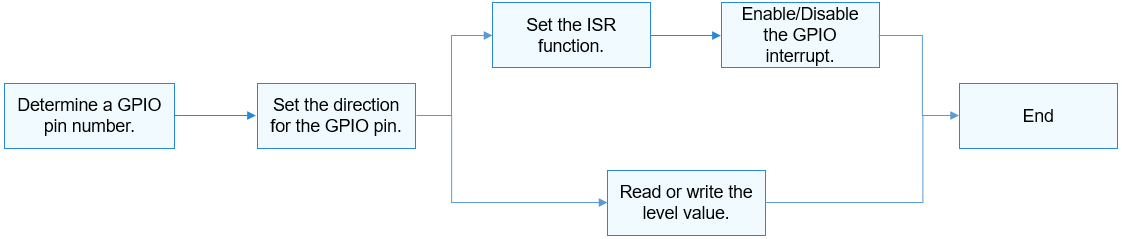
The GPIO APIs use the GPIO pin number to specify a pin. Figure 1 shows the general process of using a GPIO.
Figure 1 Process of using a GPIO
Determining a GPIO Pin Number
The method for converting GPIO pin numbers varies according to the GPIO controller model, parameters, and controller driver of different system on chips (SoCs).
-
Hi3516D V300
A controller manages 12 groups of GPIO pins. Each group contains 8 GPIO pins.
GPIO pin number = GPIO group index (0-11) x Number of GPIO pins in each group (8) + Offset in the group
Example: GPIO number of GPIO10_3 = 10 x 8 + 3 = 83
-
Hi3518E V300
A controller manages 10 groups of GPIO pins. Each group contains 10 GPIO pins.
GPIO pin number = GPIO group index (0–9) x Number of GPIO pins in each group (10) + Offset in the group
Example: GPIO pin number of GPIO7_3 = 7 x 10 + 3 = 73
Using APIs to Operate GPIO Pins
-
Set the direction for a GPIO pin.
Before performing read/write operations on a GPIO pin, call the following function to set the direction:
int32_t GpioSetDir(uint16_t gpio, uint16_t dir);
Table 1 Description of GpioSetDir
-
Read or write the level value for a GPIO pin.
To read the level value of a GPIO pin, call the following function:
int32_t GpioRead(uint16_t gpio, uint16_t *val);
Table 2 Description of GpioRead
To write the level value for a GPIO pin, call the following function:
int32_t GpioWrite(uint16_t gpio, uint16_t val);
Table 3 Description of GpioWrite
Example:
int32_t ret; uint16_t val; /* Set the output direction for GPIO3. */ ret = GpioSetDir(3, GPIO_DIR_OUT); if (ret != 0) { HDF_LOGE("GpioSerDir: failed, ret %d\n", ret); return; } /* Write the low level GPIO_VAL_LOW for GPIO3. */ ret = GpioWrite(3, GPIO_VAL_LOW); if (ret != 0) { HDF_LOGE("GpioWrite: failed, ret %d\n", ret); return; } /* Set the input direction for GPIO6. */ ret = GpioSetDir(6, GPIO_DIR_IN); if (ret != 0) { HDF_LOGE("GpioSetDir: failed, ret %d\n", ret); return; } /* Read the level value of GPIO6. */ ret = GpioRead(6, &val); -
Set the ISR function for a GPIO pin.
To set the ISR function for a GPIO pin, call the following function:
int32_t GpioSetIrq(uint16_t gpio, uint16_t mode, GpioIrqFunc func, void *arg);
Table 4 Description of GpioSetIrq
 CAUTION:
Only one ISR function can be set for a GPIO pin at a time. If GpioSetIrq is called repeatedly, the previous IRS function will be replaced.
CAUTION:
Only one ISR function can be set for a GPIO pin at a time. If GpioSetIrq is called repeatedly, the previous IRS function will be replaced.If the ISR function is no longer required, call the following function to cancel the setting:
int32_t GpioUnSetIrq(uint16_t gpio);
Table 5 Description of GpioUnSetIrq
After the ISR function is set, call the following function to enable a GPIO interrupt:
int32_t GpioEnableIrq(uint16_t gpio);
Table 6 Description of GpioEnableIrq
CAUTION:
The configured ISR function can be responded only after the ISR function is enabled.Use the following function to disable the GPIO interrupt:
int32_t GpioDisableIrq(uint16_t gpio);
Table 7 Description of GpioDisableIrq
Example:
/* ISR function */
*/
int32_t MyCallBackFunc(uint16_t gpio, void *data)
{
    HDF_LOGI("%s: gpio:%u interrupt service in! data=%p\n", __func__, gpio, data);
    return 0;
}

int32_t ret;
/* Set the ISR function to MyCallBackFunc, the parameter to NULL, and the interrupt trigger mode to rising edge. */
ret = GpioSetIrq(3, OSAL_IRQF_TRIGGER_RISING, MyCallBackFunc, NULL);
if (ret != 0) {
    HDF_LOGE("GpioSetIrq: failed, ret %d\n", ret);
    return;
}

/* Enable an interrupt for GPIO3. */
ret = GpioEnableIrq(3);
if (ret != 0) {
    HDF_LOGE("GpioEnableIrq: failed, ret %d\n", ret);
    return;
}

/* Disable the interrupt for GPIO3. */
ret = GpioDisableIrq(3);
if (ret != 0) {
    HDF_LOGE("GpioDisableIrq: failed, ret %d\n", ret);
    return;
}

/* Cancel the ISR function for GPIO3. */
ret = GpioUnSetIrq(3);
if (ret != 0) {
    HDF_LOGE("GpioUnSetIrq: failed, ret %d\n", ret);
    return;
}