GPIO
Overview
Function
A general-purpose input/output (GPIO) controller manages all GPIO pins by group. Each group of GPIO pins is associated with one or more registers. The GPIO controller manages the pins by reading data from and writing data to the registers.
Basic Concepts
A GPIO can be used as an input, an output, or both, and is controllable by software.
-
GPIO input
When a GPIO is used as an input, it reads the level state (high or low) of each pin. Common input modes include analog input, floating input, pull-up input, and pull-down input.
-
GPIO output
When a GPIO is used as an output, it sets the pin level. Common output modes include open-drain output, push-pull output, multiplexed open-drain output, and multiplexed push-pull output.
Working Principles
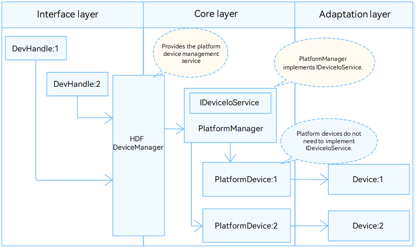
In the Hardware Driver Foundation (HDF), the GPIO module uses the unified service mode for API adaptation. In this mode, a device service is used as the GPIO manager to handle access requests from the devices of the same type in a unified manner. The unified service mode applies to the scenario where there are many device objects of the same type. If the independent service mode is used in this case, more device nodes need to be configured and more memory resources will be consumed. The following figure shows the unified service mode.
In the unified service mode, the core layer manages all controllers in a unified manner and publishes a service for the interface layer. That is, the driver does not need to publish a service for each controller.
The GPIO module is divided into the following layers:
- Interface layer: provides APIs for operating GPIO pins.
- Core layer: provides the capabilities of adding and removing a GPIO controller and managing GPIO pins. This layer interacts with the adaptation layer through hook functions to allow the GPIO chip drivers of different vendors to quickly access the HDF.
- Adaptation layer: instantiates hook functions to implement specific features.
Figure 1 Unified service mode
Development Guidelines
When to Use
As a concept at the software layer, GPIO is used to manage GPIO pin resources. You can use the APIs provided by the GPIO module to control pins. Before using your GPIO driver with OpenHarmony, you need to perform GPIO driver adaptation. The following sections describe how to adapt the GPIO driver.
Available APIs
To enable the upper layer to successfully operate GPIO pins by calling the GPIO APIs, hook functions are defined in //drivers/hdf_core/framework/support/platform/include/gpio/gpio_core.h for the core layer. You need to implement these hook functions at the adaptation layer and hook them to implement the interaction between the interface layer and the core layer.
GpioMethod:
struct GpioMethod {
    int32_t (*request)(struct GpioCntlr *cntlr, uint16_t local);                // Reserved.
    int32_t (*release)(struct GpioCntlr *cntlr, uint16_t local);                // Reserved.
    int32_t (*write)(struct GpioCntlr *cntlr, uint16_t local, uint16_t val);
    int32_t (*read)(struct GpioCntlr *cntlr, uint16_t local, uint16_t *val);
    int32_t (*setDir)(struct GpioCntlr *cntlr, uint16_t local, uint16_t dir);
    int32_t (*getDir)(struct GpioCntlr *cntlr, uint16_t local, uint16_t *dir);
    int32_t (*toIrq)(struct GpioCntlr *cntlr, uint16_t local, uint16_t *irq);   // Reserved.
    int32_t (*setIrq)(struct GpioCntlr *cntlr, uint16_t local, uint16_t mode, GpioIrqFunc func, void *arg);
    int32_t (*unsetIrq)(struct GpioCntlr *cntlr, uint16_t local);
    int32_t (*enableIrq)(struct GpioCntlr *cntlr, uint16_t local);
    int32_t (*disableIrq)(struct GpioCntlr *cntlr, uint16_t local);
}
Table 1 Hook functions in GpioMethod
| Function | Input Parameter | Output Parameter | Return Value | Description |
|---|---|---|---|---|
| write | cntlr: structure pointer to the GPIO controller at the core layer. local: GPIO port number, which is of the uint16_t type. val: level value to write, which is of the uint16_t type. |
– | HDF_STATUS | Writes the level for a GPIO pin. |
| read | cntlr: structure pointer to the GPIO controller at the core layer. local: GPIO port number, which is of the uint16_t type. |
val: level value read, which is of the uint16_t type. | HDF_STATUS | Reads the level of a GPIO pin. |
| setDir | cntlr: structure pointer to the GPIO controller at the core layer. local: GPIO port number, which is of the uint16_t type. dir: pin direction to set, which is of the uint16_t type. |
– | HDF_STATUS | Sets the direction (input or output) for a GPIO pin. |
| getDir | cntlr: structure pointer to the GPIO controller at the core layer. local: GPIO port number, which is of the uint16_t type. |
dir: pin direction read, which is of the uint16_t type. | HDF_STATUS | Obtains the input or output direction of a GPIO pin. |
| setIrq | cntlr: structure pointer to the GPIO controller at the core layer. local: GPIO port number, which is of the uint16_t type. mode: interrupt trigger mode, which can be edge or level. The value is of the uint16_t type. func: pointer to the interrupt request (IRQ) handler. arg: void pointer to the input parameters of the IRQ handler. |
– | HDF_STATUS | Sets an IRQ function for a GPIO pin. |
| unsetIrq | cntlr: structure pointer to the GPIO controller at the core layer. local: GPIO port number, which is of the uint16_t type. |
– | HDF_STATUS | Cancels the IRQ function for a GPIO pin. |
| enableIrq | cntlr: structure pointer to the GPIO controller at the core layer. local: GPIO port number, which is of the uint16_t type. |
– | HDF_STATUS | Enables interrupts for a GPIO pin. |
| disableIrq | cntlr: structure pointer to the GPIO controller at the core layer. local: GPIO port number, which is of the uint16_t type. |
– | HDF_STATUS | Disables interrupts for a GPIO pin. |
How to Develop
The GPIO module adaptation procedure is as follows:
- Instantiate the driver entry.
- Configure attribute files.
- Instantiate the GPIO controller object.
- Debug the driver.
Example
The following uses the //device_soc_hisilicon/common/platform/gpio/gpio_hi35xx.c driver of the Hi3516D V300 development board as an example to describe the driver adaptation.
-
Instantiate the driver entry.
The driver entry must be a global variable of the HdfDriverEntry type (defined in hdf_device_desc.h), and the value of moduleName must be the same as that in device_info.hcs. In the HDF, the start address of each HdfDriverEntry object of all loaded drivers are collected to form a segment address space similar to an array for the upper layer to invoke. Generally, the HDF calls the Bind function and then the Init function to load a driver. If Init fails to be called, the HDF calls Release to release driver resources and exit.
GPIO driver entry example:
struct HdfDriverEntry g_gpioDriverEntry = { .moduleVersion = 1, .Bind = Pl061GpioBind, // GPIO does not use the Bind function, which is an empty implementation in this example. You can add related operations as required. ..Init = Pl061GpioInit, // See the Init function. .Release = Pl061GpioRelease, // See the Release function. .moduleName = "hisi_pl061_driver", // (Mandatory) The value must be the same as that of moduleName in the .hcs file. }; HDF_INIT(g_gpioDriverEntry); // Call HDF_INIT to register the driver entry with the HDF. -
Configure attribute files.
Add the deviceNode information to the device_info.hcs file. The deviceNode information is closely related to driver entry registration. In this example, there is only one GPIO controller. If there are multiple GPIO controllers, add the deviceNode information to the device_info.hcs file for each controller. The device attribute values are closely related to the default values or value ranges of the GpioCntlr members at the core layer, and are configured in gpio_config.hcs.
-
device_info.hcs example
Add the deviceNode information to the //vendor/hisilicon/hispark_taurus/hdf_config/device_info/device_info.hcs file.
root { device_info { platform :: host { hostName = "platform_host"; priority = 50; device_gpio :: device { device0 :: deviceNode { policy = 0; // The value 0 indicates that no service needs to be published. priority = 10; // Driver startup priority. permission = 0644; // Permission for the device node created. oduleName = "hisi_pl061_driver"; // (Mandatory) Driver name, which must be the same as moduleName in the driver entry. deviceMatchAttr = "hisilicon_hi35xx_pl061"; // (Mandatory) Private data of the controller. The value must be the same as the controller information in gpio_config.hcs. // The private information about all controllers is in the gpio_config.hcs file. } } } } } -
gpio_config.hcs example
Configure the device attributes in the //device/soc/hisilicon/hi3516dv300/sdk_liteos/hdf_config/gpio/gpio_config.hcs file. The parameters are as follows:
root {
    platform {
        gpio_config {
            controller_0x120d0000 {
                match_attr = "hisilicon_hi35xx_pl061";   // (Mandatory) The value must be the same as that of deviceMatchAttr in device_info.hcs.
                groupNum = 12;                           // (Mandatory) GPIO group number.
                bitNum = 8;                              // (Mandatory) Number of GPIO pins in each group.
                regBase = 0x120d0000;                    // (Mandatory) Physical base address.
                regStep = 0x1000;                        // (Mandatory) Register offset step.
                irqStart = 48;                           // (Mandatory) Enable interrupts.
                irqShare = 0;                            // (Mandatory) Whether to share interrupt. The value 1 means to share interrupt; the value 0 means the opposite.
            }
            ...
        }
    }
}
After the gpio_config.hcs file is configured, include the file in the hdf.hcs file. Otherwise, the configuration file cannot take effect.
#include "../../../../device/soc/hisilicon/hi3516dv300/sdk_liteos/hdf_config/gpio/gpio_config.hcs" // Relative path of the gpio_config.hcs file.
-
-
Instantiate the GPIO controller object.
Initialize the GpioCntlr object at the core layer, including defining a custom structure (to pass parameters and data) and implementing the HdfDriverEntry member functions (Bind, Init and Release) to instantiate GpioMethod in GpioCntlr (so that the underlying driver functions can be called).
-
Define a custom structure.
To the driver, the custom structure holds parameters and data. The DeviceResourceIface method provided by the HDF reads the values in the gpio_config.hcs file to initialize the members in the custom structure and passes important parameters, such as the GPIO group number and the number of pins, to the GpioCntlr object at the core layer.
// Define the GPIO group information. struct Pl061GpioGroup { struct GpioCntlr cntlr // (Mandatory) Control object of the core layer. volatile unsigned char *regBase; // (Mandatory) Register base address. unsigned int index; unsigned int irq; OsalIRQHandle irqFunc; OsalSpinlock lock; uint32_t irqSave; bool irqShare; struct PlatformDumper *dumper; char *dumperName; }; struct Pl061GpioData { volatile unsigned char *regBase; // (Mandatory) Register base address. uint32_t phyBase; // (Mandatory) Physical base address. uint32_t regStep;; // (Mandatory) Register offset step. uint32_t irqStart; // (Mandatory) Enable interrupts. uint16_t groupNum; // (Mandatory) Parameter of the GPIO port number. uint16_t bitNum; // (Mandatory) Parameter of the GPIO port number. uint8_t irqShare; // (Mandatory) Whether to share interrupt. struct Pl061GpioGroup *groups; // (Optional) Set as required. struct GpioInfo *gpioInfo; void *priv; }; struct GpioInfo { struct GpioCntlr *cntlr; char name[GPIO_NAME_LEN]; OsalSpinlock spin; uint32_t irqSave; struct GpioIrqRecord *irqRecord; }; // GpioCntlr is the controller structure at the core layer. The Init function assigns values to the members of GpioCntlr. struct GpioCntlr { struct PlatformDevice device; struct GpioMethod *ops; uint16_t start; uint16_t count; struct GpioInfo *ginfos; bool isAutoAlloced; void *priv; }; -
Instantiate the GpioMethod structure in GpioCntlr.
// The members of the GpioMethod structure are hook functions. You need to implement them by referring to Table 1. static struct GpioMethod g_method = { .request = NULL, .release = NULL, .write = Pl061GpioWrite, // Write the pin level. .read = Pl061GpioRead, // Read the pin level. .setDir = Pl061GpioSetDir, // Set the pin direction. .getDir = Pl061GpioGetDir, // Obtain the pin direction. .toIrq = NULL, .setIrq = Pl061GpioSetIrq, // Set an IRQ function for a pin. Skip it if this capability is not available. .unsetIrq = Pl061GpioUnsetIrq, // Cancel the IRQ function for a pin. Skip it if this capability is not available. .enableIrq = Pl061GpioEnableIrq, // Enable interrupts for a pin. Skip it if this capability is not available. .disableIrq = Pl061GpioDisableIrq, // Disable interrupts for a pin. Skip it if this capability is not available. }; -
Implement the Init function.
Input parameters:
HdfDeviceObject, a device object created by the HDF for each driver, holds device-related private data and service APIs.
Return value:
HDF_STATUS
The table below describes some status. For more information, see HDF_STATUS in the //drivers/hdf_core/framework/include/utils/hdf_base.h file.Table 2 HDF_STATUS
-
| Status | Description |
|---|---|
| HDF_ERR_INVALID_OBJECT | Invalid controller object. |
| HDF_ERR_MALLOC_FAIL | Failed to allocate memory. |
| HDF_ERR_INVALID_PARAM | Invalid parameter. |
| HDF_ERR_IO | I/O error. |
| HDF_SUCCESS | Initialization successful. |
| HDF_FAILURE | Initialization failed. |
  Function description:

  Initializes the custom structure object and **GpioCntlr**, calls **GpioCntlrAdd()** at the core layer, and (optional) accesses the virtual file system (VFS).

  ```c
  static struct Pl061GpioData g_pl061 = {
      .groups = NULL,
      .groupNum = PL061_GROUP_MAX,
      .bitNum = PL061_BIT_MAX,
  };

  static int32_t Pl061GpioInitGroups(struct Pl061GpioData *pl061)
  {
      int32_t ret;
      uint16_t i;
      struct Pl061GpioGroup *groups = NULL;

      if (pl061 == NULL) {
          return HDF_ERR_INVALID_PARAM;
      }

      groups = (struct Pl061GpioGroup *)OsalMemCalloc(sizeof(*groups) * pl061->groupNum);
      if (groups == NULL) {
          return HDF_ERR_MALLOC_FAIL;
      }
      pl061->groups = groups;

      for (i = 0; i < pl061->groupNum; i++) {
          // Initialize related information.
          groups[i].index = i;
          groups[i].regBase = pl061->regBase + i * pl061->regStep;
          groups[i].irq = pl061->irqStart + i;
          groups[i].irqShare = pl061->irqShare;
          groups[i].cntlr.start = i * pl061->bitNum;
          groups[i].cntlr.count = pl061->bitNum;
          groups[i].cntlr.ops = &g_method;
          groups[i].cntlr.ginfos = &pl061->gpioInfo[i * pl061->bitNum];

          if ((ret = OsalSpinInit(&groups[i].lock)) != HDF_SUCCESS) {
              goto ERR_EXIT;
          }

          ret = GpioCntlrAdd(&groups[i].cntlr); // Add related information to the HDF core.
          if (ret != HDF_SUCCESS) {
              HDF_LOGE("%s: err add controller(%hu:%hu):%d", __func__,
                  groups[i].cntlr.start, groups[i].cntlr.count, ret);
              (void)OsalSpinDestroy(&groups[i].lock);
              goto ERR_EXIT;
          }
      }
      return HDF_SUCCESS;

  ERR_EXIT:
      while (i-- > 0) {
          GpioCntlrRemove(&groups[i].cntlr);
          (void)OsalSpinDestroy(&groups[i].lock);
      }
      pl061->groups = NULL;
      OsalMemFree(groups);
      return ret;
  }

  static int32_t Pl061GpioInit(struct HdfDeviceObject *device)
  {
      int32_t ret;
      struct Pl061GpioData *pl061 = &g_pl061;

      if (device == NULL || device->property == NULL) {
          HDF_LOGE("%s: device or property null!", __func__);
          return HDF_ERR_INVALID_OBJECT;
      }

      pl061->gpioInfo = OsalMemCalloc(sizeof(struct GpioInfo) * GPIO_MAX_INFO_NUM);
      if (pl061->gpioInfo == NULL) {
          HDF_LOGE("%s: failed to calloc gpioInfo!", __func__);
          return HDF_ERR_MALLOC_FAIL;
      }

      ret = Pl061GpioReadDrs(pl061, device->property);// Use the attribute values read from the gpio_config.hcs file to initialize the members of the custom structure object.
      if (ret != HDF_SUCCESS) {
          HDF_LOGE("%s: failed to read drs:%d", __func__, ret);
          return ret;
      }

      if (pl061->groupNum > PL061_GROUP_MAX || pl061->groupNum <= 0 ||
          pl061->bitNum > PL061_BIT_MAX || pl061->bitNum <= 0) {
          HDF_LOGE("%s: err groupNum:%hu, bitNum:%hu", __func__, pl061->groupNum, pl061->bitNum);
          return HDF_ERR_INVALID_PARAM;
      }

      pl061->regBase = OsalIoRemap(pl061->phyBase, pl061->groupNum * pl061->regStep);// Create address mapping.
      if (pl061->regBase == NULL) {
          HDF_LOGE("%s: err remap phy:0x%x", __func__, pl061->phyBase);
          return HDF_ERR_IO;
      }

      ret = Pl061GpioInitGroups(pl061); // Initialize the group information and add it to the HDF core layer.
      if (ret != HDF_SUCCESS) {
          HDF_LOGE("%s: err init groups:%d", __func__, ret);
          OsalIoUnmap((void *)pl061->regBase);
          pl061->regBase = NULL;
          return ret;
      }
      pl061->priv = (void *)device->property;
      device->priv = (void *)pl061;
      Pl061GpioDebug(pl061);

  #ifdef PL061_GPIO_USER_SUPPORT
      if (GpioAddVfs(pl061->bitNum) != HDF_SUCCESS) {
          HDF_LOGE("%s: add vfs fail!", __func__);
      }
  #endif
      HDF_LOGI("%s: dev service:%s init success!", __func__, HdfDeviceGetServiceName(device));
      return HDF_SUCCESS;
  }
  ```
-
Implement the Release function.
Input parameters:
HdfDeviceObject, a device object created by the HDF for each driver, holds device-related private data and service APIs.
Return value:
No value is returned.
Function description:
Releases the memory and deletes the controller. This function assigns values to Release() in the driver entry structure. If the HDF fails to call Init() to initialize the driver, Release() is called to release driver resources.
 NOTE
NOTEAll forced conversion operations for obtaining the corresponding object can be successful only when the Init function has the value assignment operations.
static void Pl061GpioUninitGroups(struct Pl061GpioData *pl061)
{
    uint16_t i;
    struct Pl061GpioGroup *group = NULL;

    for (i = 0; i < pl061->groupNum; i++) {
        group = &pl061->groups[i];
        GpioDumperDestroy(&pl061->groups[i]);
        GpioCntlrRemove(&group->cntlr); // Remove from the HDF core layer.
    }

    OsalMemFree(pl061->groups);
    pl061->groups = NULL;
}

static void Pl061GpioRelease(struct HdfDeviceObject *device)
{
    struct Pl061GpioData *pl061 = NULL;

    HDF_LOGI("%s: enter", __func__);
    if (device == NULL) {
        HDF_LOGE("%s: device is null!", __func__);
        return;
    }

#ifdef PL061_GPIO_USER_SUPPORT
    GpioRemoveVfs();
#endif

    pl061 = (struct Pl061GpioData *)device->priv;
    if (pl061 == NULL) {
        HDF_LOGE("%s: device priv is null", __func__);
        return;
    }

    Pl061GpioUninitGroups(pl061);
    OsalMemFree(pl061->gpioInfo);
    pl061->gpioInfo = NULL;
    OsalIoUnmap((void *)pl061->regBase);
    pl061->regBase = NULL;
}
-
Debug the driver.
(Optional) For new drivers, verify the basic functions, such as the GPIO status control and response to interrupts.