GPIO
Overview
Generally, a general-purpose input/output (GPIO) controller manages all GPIO pins by group. Each group of GPIO pins is associated with one or more registers. The GPIO pins are operated by reading data from and writing data to the registers.
The GPIO APIs define a set of standard functions for performing operations on GPIO pins, including:
-
Setting the pin direction, which can be input or output (High impedance is not supported currently.)
-
Reading and writing level values, which can be low or high
-
Setting an interrupt service routine (ISR) function and interrupt trigger mode for a pin
-
Enabling or disabling a pin interrupt
Available APIs
Table 1 APIs available for the GPIO driver
NOTE: All functions provided in this document can be called only in kernel mode.
Usage Guidelines
How to Use
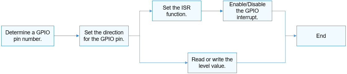
The GPIO APIs use the GPIO pin number to specify a pin. Figure 1 shows the general process of using a GPIO.
Figure 1 Process of using a GPIO
Determining a GPIO Pin Number
The method for converting GPIO pin numbers varies according to the GPIO controller model, parameters, and controller driver of different system on chips (SoCs).
-
Hi3516DV300
A controller manages 12 groups of GPIO pins. Each group contains 8 GPIO pins.
GPIO pin number = GPIO group index (0–11) x Number of GPIO pins in each group (8) + Offset in the group
Example: GPIO number of GPIO10_3 = 10 x 8 + 3 = 83
-
Hi3518EV300
A controller manages 10 groups of GPIO pins. Each group contains 10 GPIO pins.
GPIO pin number = GPIO group index (0–9) x Number of GPIO pins in each group (10) + Offset in the group
Example: GPIO pin number of GPIO7_3 = 7 x 10 + 3 = 73
Using APIs to Operate GPIO Pins
-
Set the direction for a GPIO pin.
Before performing read/write operations on a GPIO pin, call the following function to set the direction:
int32_t GpioSetDir(uint16_t gpio, uint16_t dir);
Table 2 Description of GpioSetDir
-
Read or write the level value for a GPIO pin.
To read the level value of a GPIO pin, call the following function:
int32_t GpioRead(uint16_t gpio, uint16_t *val);
Table 3 Description of GpioRead
To write the level value for a GPIO pin, call the following function:
int32_t GpioWrite(uint16_t gpio, uint16_t val);
Table 4 Description of GpioWrite
Example:
int32_t ret; uint16_t val; /* Set the output direction for GPIO3. */ ret = GpioSetDir(3, GPIO_DIR_OUT); if (ret != 0) { HDF_LOGE("GpioSerDir: failed, ret %d\n", ret); return; } /* Write the low level GPIO_VAL_LOW for GPIO3. */ ret = GpioWrite(3, GPIO_VAL_LOW); if (ret != 0) { HDF_LOGE("GpioWrite: failed, ret %d\n", ret); return; } /* Set the input direction for GPIO6. */ ret = GpioSetDir(6, GPIO_DIR_IN); if (ret != 0) { HDF_LOGE("GpioSetDir: failed, ret %d\n", ret); return; } /* Read the level value of GPIO6. */ ret = GpioRead(6, &val); -
Set the ISR function for a GPIO pin.
To set the ISR function for a GPIO pin, call the following function:
int32_t GpioSetIrq(uint16_t gpio, uint16_t mode, GpioIrqFunc func, void *arg);
Table 5 Description of GpioSetIrq
 CAUTION:
Only one ISR function can be set for a GPIO pin at a time. If GpioSetIrq is called repeatedly, the previous IRS function will be replaced.
CAUTION:
Only one ISR function can be set for a GPIO pin at a time. If GpioSetIrq is called repeatedly, the previous IRS function will be replaced.If the ISR function is no longer required, call the following function to cancel the setting:
int32_t GpioUnSetIrq(uint16_t gpio);
Table 6 Description of GpioUnSetIrq
After the ISR function is set, call the following function to enable a GPIO interrupt:
int32_t GpioEnableIrq(uint16_t gpio);
Table 7 Description of GpioEnableIrq
CAUTION:
The configured ISR function can be responded only after the GPIO interrupt is enabled.Use the following function to disable the GPIO interrupt:
int32_t GpioDisableIrq(uint16_t gpio);
Table 8 Description of GpioDisableIrq
Example:
/* ISR function */
*/
int32_t MyCallBackFunc(uint16_t gpio, void *data)
{
    HDF_LOGI("%s: gpio:%u interrupt service in! data=%p\n", __func__, gpio, data);
    return 0;
}

int32_t ret;
/* Set the ISR function to MyCallBackFunc, the parameter to NULL, and the interrupt trigger mode to rising edge. */
ret = GpioSetIrq(3, OSAL_IRQF_TRIGGER_RISING, MyCallBackFunc, NULL);
if (ret != 0) {
    HDF_LOGE("GpioSetIrq: failed, ret %d\n", ret);
    return;
}

/* Enable an interrupt for GPIO3. */
ret = GpioEnableIrq(3);
if (ret != 0) {
    HDF_LOGE("GpioEnableIrq: failed, ret %d\n", ret);
    return;
}

/* Disable the interrupt for GPIO3. */
ret = GpioDisableIrq(3);
if (ret != 0) {
    HDF_LOGE("GpioDisableIrq: failed, ret %d\n", ret);
    return;
}

/* Cancel the ISR function for GPIO3. */
ret = GpioUnSetIrq(3);
if (ret != 0) {
    HDF_LOGE("GpioUnSetIrq: failed, ret %d\n", ret);
    return;
}
Usage Example
In this example, we test the interrupt trigger of a GPIO pin as follows: Set the ISR function for the pin, set the trigger mode to rising edge and failing edge, write high and low levels to the pin alternately to generate level fluctuation, and observe the execution of the ISR function.
Select an idle GPIO pin. This example uses a Hi3516D V300 development board and GPIO pin GPIO10_3, which is numbered GPIO83.
You can select an idle GPIO pin based on the development board and schematic diagram.
#include "gpio_if.h"
#include "hdf_log.h"
#include "osal_irq.h"
#include "osal_time.h"

static uint32_t g_irqCnt;

/* ISR function */
static int32_t TestCaseGpioIrqHandler(uint16_t gpio, void *data)
{
    HDF_LOGE("%s: irq triggered! on gpio:%u, data=%p", __func__, gpio, data);
    g_irqCnt++; /* If the ISR function is triggered, the number of global interrupts is incremented by 1. */
    return GpioDisableIrq(gpio);
}

/* Test case function */
static int32_t TestCaseGpioIrqEdge(void)
{
    int32_t ret;
    uint16_t valRead;
    uint16_t mode;
    uint16_t gpio = 83; /* Number of the GPIO pin to test */
    uint32_t timeout;

    /* Set the output direction for the pin. */
    ret = GpioSetDir(gpio, GPIO_DIR_OUT);
    if (ret != HDF_SUCCESS) {
        HDF_LOGE("%s: set dir fail! ret:%d\n", __func__, ret);
        return ret;
    }

    /* Disable the interrupt of the pin. */
    ret = GpioDisableIrq(gpio);
    if (ret != HDF_SUCCESS) {
        HDF_LOGE("%s: disable irq fail! ret:%d\n", __func__, ret);
        return ret;
    }

    /* Set the ISR function for the pin. The trigger mode is both rising edge and falling edge. */
    mode = OSAL_IRQF_TRIGGER_RISING | OSAL_IRQF_TRIGGER_FALLING;
    HDF_LOGE("%s: mode:%0x\n", __func__, mode);
    ret = GpioSetIrq(gpio, mode, TestCaseGpioIrqHandler, NULL);
    if (ret != HDF_SUCCESS) {
        HDF_LOGE("%s: set irq fail! ret:%d\n", __func__, ret);
        return ret;
    }

    /* Enable the interrupt for this pin. */
    ret = GpioEnableIrq(gpio);
    if (ret != HDF_SUCCESS) {
        HDF_LOGE("%s: enable irq fail! ret:%d\n", __func__, ret);
        (void)GpioUnSetIrq(gpio);
        return ret;
    }

    g_irqCnt = 0; /* Reset the global counter. */
    timeout = 0;  /* Reset the waiting time. */
    /* Wait for the ISR function of this pin to trigger. The timeout duration is 1000 ms. */
    while (g_irqCnt <= 0 && timeout < 1000) {
        (void)GpioRead(gpio, &valRead);
        (void)GpioWrite(gpio, (valRead == GPIO_VAL_LOW) ? GPIO_VAL_HIGH : GPIO_VAL_LOW);
        HDF_LOGE("%s: wait irq timeout:%u\n", __func__, timeout);
        OsalMDelay(200); /* wait for irq trigger */
        timeout += 200;
    }
    (void)GpioUnSetIrq(gpio);
    return (g_irqCnt > 0) ? HDF_SUCCESS : HDF_FAILURE;
}