Setting Up WLAN Connection
This example shows how to connect the WLAN module to the gateway using attention (AT) commands.
Building Source Code
This section describes how to perform the WLAN module building on a Linux server.
If the Linux environment is installed using Docker, perform the building by referring to Using Docker to Prepare the Build Environment. If the Linux environment is installed using a software package, perform the following steps:
-
Open the HUAWEI DevEco Device Tool and choose View > Terminal.
Figure 1 Starting the IDE terminal tool

On the TERMINAL panel, run the ssh command, for example, ssh user@ipaddr, to connect to the Linux server.
-
Go to the root directory of the code, run the hb set and . commands on the TERMINAL panel, and select the wifiiot_hispark_pegasus version.
-
Run the hb build command to start building.
-
Check whether the building is successful. If yes, wifiiot_hispark_pegasus build success will be displayed, as shown in the following figure.
-
Check whether the following files are generated in the ./out/wifiiot/ directory.
ls -l out/hispark_pegasus/wifiiot_hispark_pegasus/


Burning Images
Programming the flash memory is the process of downloading compiled program files to a chipset development board to provide a basis for subsequent debugging. With the one-click flash memory programming function of DevEco Device Tool, you can program flash memory on development boards quickly and efficiently.
The Hi3861 V100 development board allows you to program flash memory through the serial port using the burn-serial or hiburn-serial protocol. The hiburn-serial protocol is applicable to both Windows and Linux systems, while the burn-serial is applicable to Linux only.
NOTE: The burn-serial protocol is used for compatibility with the projects of historical versions. It does not differ from hiburn-serial in operations.
The operations for programming flash memory in Windows and Linux are the same. The only difference lies in the environment setup for DevEco Device Tool.
-
Connect the PC and the target development board through the USB port. For details, see Introduction to the Hi3861 Development Board.
-
Open Device Manager, then check and record the serial port number corresponding to the development board.
NOTE:
If the serial port number is not displayed correctly, follow the steps described in Installing the Serial Port Driver on the Hi3861 Series Development Board.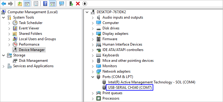
-
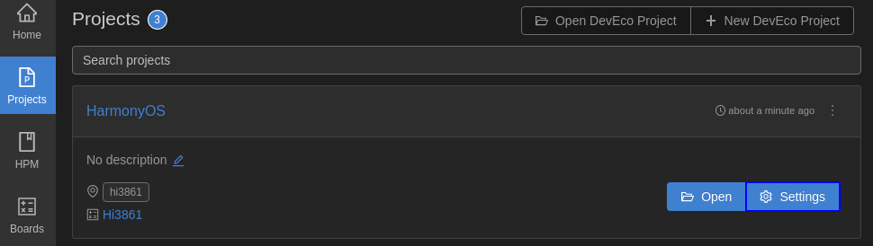
Open DevEco Device Tool and go to Projects > Settings.
-
On the Partition Configuration tab page, modify the settings. In general cases, you can leave the fields at their default settings.
-
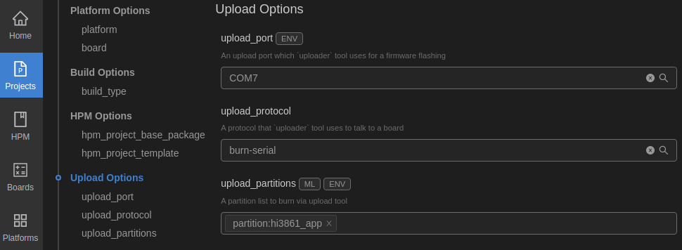
On the hi3861 tab page, set the programming options.
- upload_port: Select the serial port number obtained in step 2.
- upload_protocol: Select the programming protocol. For Windows, set this parameter to burn-serial or hiburn-serial. For Linux, set this parameter to hiburn-serial.
- upload_partitions: Select the file to be programmed. hi3861_app is selected by default.
-
When you finish modifying, click Save in the upper right corner.
-
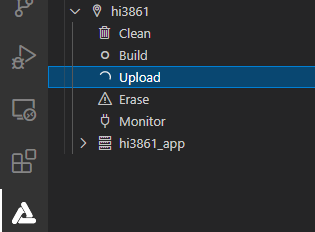
Open the project file. In the DevEco Device Tool window, go to PROJECT TASKS > hi3861 > Upload to start programming.
-
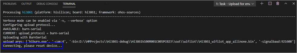
When the following information is displayed, press the RST button on the development board to restart it.
-
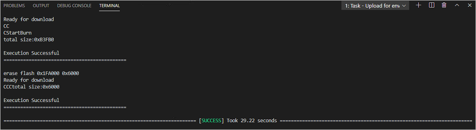
Start programming. If the following message is displayed, it indicates that the programming is successful.
Connecting WLAN Module to the Internet.
After completing version building and burning, do as follows to connect the WLAN module to the Internet using AT commands.
-
Click the icon of DevEco: Serial Monitor at the bottom of DevEco Studio to keep the connection between the Windows workstation and the WLAN module.
-
Reset the WLAN module. The message ready to OS start is displayed on the TERMINAL panel, indicating that the WLAN module is started successfully.
-
Run the following AT commands in sequence via the DevEco serial port terminal to start the STA mode, connect to the specified AP, and enable Dynamic Host Configuration Protocol (DHCP).
AT+STARTSTA # Start the STA mode. AT+SCAN # Scan for available APs. AT+SCANRESULT # Display the scanning result. AT+CONN="SSID",,2,"PASSWORD" # Connect to the specified AP. (SSID and PASSWORD represent the name and password of the hotspot to be connected, respectively.) AT+STASTAT # View the connection result. AT+DHCP=wlan0,1 # Request the IP address of wlan0 from the AP using DHCP. -
Check whether the WLAN module is properly connected to the gateway, as shown in the following figure.
AT+IFCFG                                # View the IP address assigned to an interface of the module.
AT+PING=X.X.X.X                         # Check the connectivity between the module and the gateway. Replace X.X.X.X with the actual gateway address.


