Running a Hello OHOS Program
This section describes how to create, compile, burn, and run the first program, and finally print Hello OHOS! on the develop board.
Creating a Program
-
Create a directory and the program source code.
Create the applications/sample/camera/apps/src/helloworld.c directory and file whose code is shown in the following example. You can customize the content to be printed. For example, you can change OHOS to World. You can use either C or C++ to develop a program.
#include <stdio.h> int main(int argc, char **argv) { printf("\n************************************************\n"); printf("\n\t\tHello OHOS!\n"); printf("\n************************************************\n\n"); return 0; } -
Create a build file.
Create the applications/sample/camera/apps/BUILD.gn file. The file content is as follows:
import("//build/lite/config/component/lite_component.gni") lite_component("hello-OHOS") { features = [ ":helloworld" ] } executable("helloworld") { output_name = "helloworld" sources = [ "src/helloworld.c" ] include_dirs = [] defines = [] cflags_c = [] ldflags = [] } -
Add a component.
Add the configuration of the hello_world_app component to the build/lite/components/applications.json file. The sample code below shows some configurations defined in the applications.json file, and the code between "##start##" and "##end##" is the new configuration (Delete the rows where "##start##" and "##end##" are located after the configurations are added.)
{ "components": [ { "component": "camera_sample_communication", "description": "Communication related samples.", "optional": "true", "dirs": [ "applications/sample/camera/communication" ], "targets": [ "//applications/sample/camera/communication:sample" ], "rom": "", "ram": "", "output": [], "adapted_kernel": [ "liteos_a" ], "features": [], "deps": { "components": [], "third_party": [] } }, ##start## { "component": "hello_world_app", "description": "Communication related samples.", "optional": "true", "dirs": [ "applications/sample/camera/apps" ], "targets": [ "//applications/sample/camera/apps:hello-OHOS" ], "rom": "", "ram": "", "output": [], "adapted_kernel": [ "liteos_a" ], "features": [], "deps": { "components": [], "third_party": [] } }, ##end## { "component": "camera_sample_app", "description": "Camera related samples.", "optional": "true", "dirs": [ "applications/sample/camera/launcher", "applications/sample/camera/cameraApp", "applications/sample/camera/setting", "applications/sample/camera/gallery", "applications/sample/camera/media" ], -
Modify the board configuration file.
Add the hello_world_app component to the vendor/hisilicon/hispark_aries/config.json file. The sample code below shows the configurations of the applications subsystem, and the code between ##start## and ##end## is the new configuration (Delete the rows where ##start## and ##end## are located after the configurations are added.)
      {
        "subsystem": "applications",
        "components": [
##start##
          { "component": "hello_world_app", "features":[] },
##end##
          { "component": "camera_sample_app", "features":[] }

        ]
      },
Building
If the Linux environment is installed using Docker, perform the building by referring to Using Docker to Prepare the Build Environment. If the Linux environment is installed using a software package, go to the root directory of the source code and run the following commands for source code compilation:
hb set (Set the building path.)
. (Select the current path.)
Select ipcamera_hispark_aries@hisilicon and press Enter.
hb build -f (Start building.)
The result files are generated in the out/hispark_aries/ipcamera_hispark_aries directory.

NOTICE: The U-Boot file of the Hi3518E V300 development board can be obtained from the following path: device/hisilicon/hispark_aries/sdk_liteos/uboot/out/boot/u-boot-hi3518ev300.bin
Burning
Programming the flash memory is the process of downloading compiled program files to a chipset development board to provide a basis for subsequent debugging. With the one-click flash memory programming function of DevEco Device Tool, you can program flash memory on development boards quickly and efficiently.
The Hi3518E V300 development board allows you to program flash memory through the USB port or serial port.
- Windows system: Supports programming through the USB port or serial port
- Linux system: Supports programming through the serial port (Linux+Windows dual system: Supports programming through the serial port or USB port)
Except for environment setup, the operations of programming are the same for Windows and Linux.
The following uses the USB port burning as an example.
-
Connect the PC and the target development board through the serial port and USB port. For details, see Introduction to the Hi3518 Development Board.
-
Open Device Manager, then check and record the serial port number corresponding to the development board.
 NOTE:
If the serial port number is not displayed correctly, follow the steps described in Installing the Serial Port Driver on the Hi3516 or Hi3518 Series Development Boards.
NOTE:
If the serial port number is not displayed correctly, follow the steps described in Installing the Serial Port Driver on the Hi3516 or Hi3518 Series Development Boards.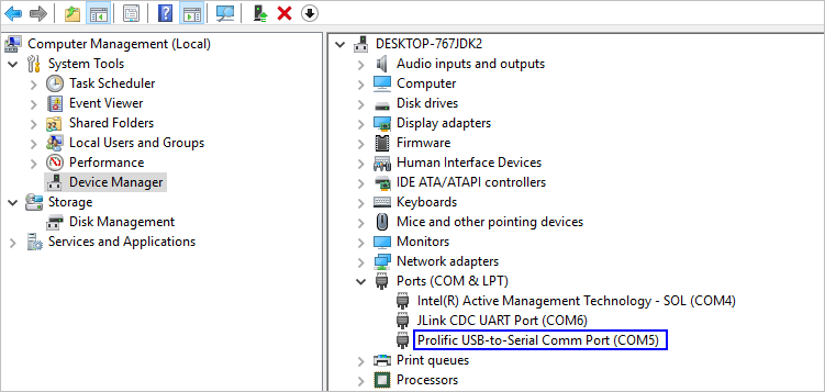
-
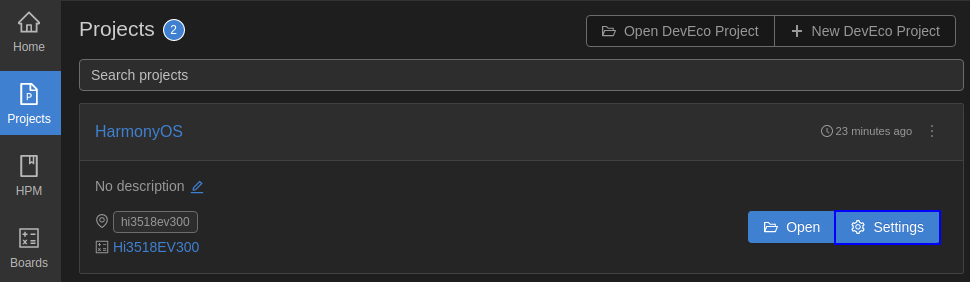
Open DevEco Device Tool and go to Projects > Settings.
-
On the Partition Configuration tab page, modify the settings. In general cases, you can leave the fields at their default settings.
-
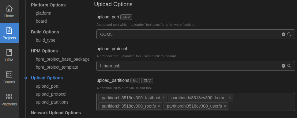
On the hi3518ev300 tab page, set the programming options.
- upload_port: Select the serial port number obtained in step 2.
- upload_protocol: Select the programming protocol hiburn-usb.
- upload_partitions: Select the file to be programmed. By default, the fastboot, kernel, rootfs, and userfs files are programmed at the same time.
-
When you finish modifying, click Save in the upper right corner.
-
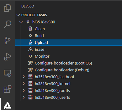
Open the project file, go to
 > PROJECT TASKS > hi3518ev300_fastboot > Erase to erase U-Boot.
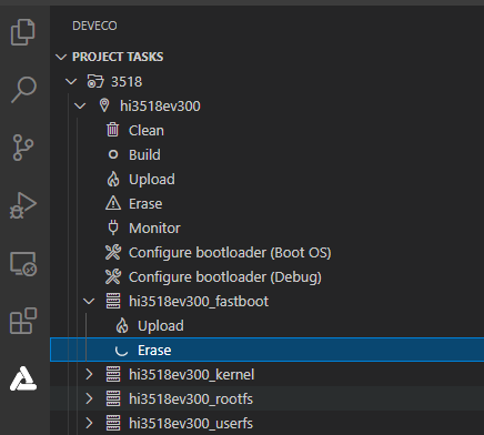
-
When the following message is displayed, power off the development board and then power it on.
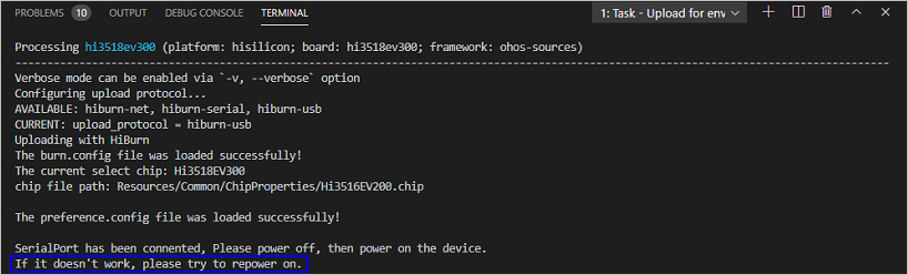
-
If the following message is displayed, it indicates that U-Boot is erased successfully.
-
Go to hi3518ev300 > Upload to start programming.
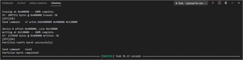
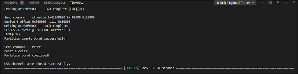
-
If the following message is displayed, it indicates that the programming is successful.
Running an Image
-
Connect to a serial port.
NOTICE:
If the connection fails, rectify the fault by referring to FAQs. -
(Mandatory for first-time burning) Modify the bootcmd and bootargs parameters of U-Boot. This step is a fixed operation and the result can be saved. However, you need to perform the following steps again if U-Boot needs to be reburnt.
Table 1 Parameters of the U-Boot
NOTICE:
go 0x40000000 (optional) indicates that the command is fixed in the startup parameters by default and the board automatically starts after it is reset. If you want to manually start the board, press Enter in the countdown phase of the U-Boot startup to interrupt the automatic startup. -
If hisilicon # is displayed during the startup, run the reset command. After the system automatically starts and OHOS is displayed, run the ./bin/helloworld command and then press Enter. The system is started successfully if information shown in the following figure is displayed.


Follow-up Learning
Congratulations! You have finished all steps! You are advised to go on learning how to develop Cameras with a Screen.