I2C
Overview
-
The Inter-Integrated Circuit (I2C) is a simple, bidirectional, and synchronous serial bus that uses merely two wires.
-
In an I2C communication, one controller communicates with one or more devices through the serial data line (SDA) and serial clock line (SCL), as shown in Figure 1.
-
I2C data transfer must begin with a START condition and end with a STOP condition. Data is transmitted byte-by-byte from the most significant bit to the least significant bit.
-
Each I2C node is recognized by a unique address and can serve as either a controller or a device. When the controller needs to communicate with a device, it writes the device address to the bus through broadcast. A device matching this address sends a response to set up a data transfer channel.
-
The I2C APIs define a set of common functions for I2C data transfer, including:
- I2C controller management: opening or closing an I2C controller
- I2C message transfer: custom transfer by using a message array

Available APIs
Table 1 APIs available for the I2C driver
NOTE: All functions provided in this document can be called only in kernel mode.
Usage Guidelines
How to Use
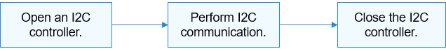
Figure 2 illustrates the process of an I2C device.
Figure 2 Process of using an I2C device
Opening an I2C Controller
Call the following function to open an I2C controller:
DevHandle I2cOpen(int16_t number);
Table 2 Description of I2cOpen
This example assumes that the system has eight I2C controllers (numbered from 0 to 7) and I2C controller 3 is to open.
DevHandle i2cHandle = NULL; /* I2C controller handle */

/* Open an I2C controller. */
i2cHandle = I2cOpen(3);
if (i2cHandle == NULL) {
    HDF_LOGE("I2cOpen: failed\n");
    return;
}
Performing I2C Communication
Use the following function for message transfer:
int32_t I2cTransfer(DevHandle handle, struct I2cMsg *msgs, int16_t count);
Table 3 Description of I2cTransfer
Number of message structures that are successfully transmitted. |
|
The type of an I2C message transfer is defined by I2cMsg. Each message structure indicates a read or write operation. Multiple read or write operations can be performed by using a message array.
int32_t ret;
uint8_t wbuff[2] = { 0x12, 0x13 };
uint8_t rbuff[2] = { 0 };
struct I2cMsg msgs[2]; /* Custom message array for transfer */
msgs[0].buf = wbuff;    /* Data to write */
msgs[0].len = 2;        /* The length of the data to write is 2. */
msgs[0].addr = 0x5A;    /* The address of the device to write the data is 0x5A. */
msgs[0].flags = 0;      /* The flag is 0, indicating the write operation. */
msgs[1].buf = rbuff;    /* Data to read */
msgs[1].len = 2;        /* The length of the data to read is 2. */
msgs[1].addr = 0x5A;    /* The address of the device to read is 0x5A. */
msgs[1].flags = I2C_FLAG_READ /* I2C_FLAG_READ is configured, indicating the read operation. */
/* Perform a custom transfer to transfer two messages. */
ret = I2cTransfer(i2cHandle, msgs, 2);
if (ret != 2) {
    HDF_LOGE("I2cTransfer: failed, ret %d\n", ret);
    return;
}
CAUTION:
- The device address in the I2cMsg structure does not contain the read/write flag bit. The read/write information is transferred by the read/write control bit in the member variable flags.
- The I2cTransfer function does not limit the number of message structures, which is determined by the I2C controller.
- The I2cTransfer function does not limit the data length of each message structure, which is determined by the I2C controller.
- The I2cTransfer function may cause the system to sleep and therefore cannot be called in the interrupt context.
Closing an I2C Controller
Call the following function to close the I2C controller after the communication is complete:
void I2cClose(DevHandle *handle);
Table 4 Description of I2cClose
I2cClose(i2cHandle); /* Close the I2C controller. */
Usage Example
This example describes how to use I2C APIs with an I2C device on a development board.
This example shows a simple register read/write operation on TouchPad on a Hi3516D V300 development board. The basic hardware information is as follows:
-
SoC: hi3516dv300
-
Touch IC: The I2C address is 0x38, and the bit width of Touch IC's internal register is 1 byte.
-
Schematic diagram: TouchPad is mounted to I2C controller 3. The reset pin of Touch IC is GPIO3.
In this example, first we reset Touch IC. (The development board supplies power to Touch IC by default after being powered on, and this use case does not consider the power supply). Then, we perform a read/write operation on an internal register to test whether the I2C channel is normal.
Example:
#include "i2c_if.h"          /* Header file of I2C APIs */
#include "gpio_if.h"         /* Header file of GPIO APIs */
#include "hdf_log.h"         /* Header file for log APIs */
#include "osal_io.h"         /* Header file of I/O read and write APIs */
#include "osal_time.h"       /* Header file of delay and sleep APIs */

/* Define a TP device structure to store I2C and GPIO hardware information. */
struct TpI2cDevice {
    uint16_t rstGpio;             /* Reset pin */
    uint16_t busId;               /* I2C bus ID */
    uint16_t addr;                /* I2C device address */
    uint16_t regLen;              /* Register bit width */
    DevHandle i2cHandle;  /* I2C controller handle */
};

/* I2C pin I/O configuration. For details, see the SoC register manual. */
#define I2C3_DATA_REG_ADDR 0x112f008c /* Address of the SDA pin configuration register of I2C controller 3
#define I2C3_CLK_REG_ADDR 0x112f0090 /* Address of the SCL pin configuration register of I2C controller 3
#define I2C_REG_CFG 0x5f1             /* Configuration values of SDA and SCL pins of I2C controller 3

static void TpSocIoCfg(void)
{
    /* Set the I/O function of the two pins corresponding to I2C controller 3 to I2C. */
    OSAL_WRITEL(I2C_REG_CFG, IO_DEVICE_ADDR(I2C3_DATA_REG_ADDR));
    OSAL_WRITEL(I2C_REG_CFG, IO_DEVICE_ADDR(I2C3_CLK_REG_ADDR));
}

/* Initialize the reset pin of the TP. Pull up the pin for 20 ms, pull down the pin for 50 ms, and then pull up the pin for 20 ms to complete the resetting. */
static int32_t TestCaseGpioInit(struct TpI2cDevice *tpDevice)
{
    int32_t ret;

    /* Set the output direction for the reset pin. */
    ret = GpioSetDir(tpDevice->rstGpio, GPIO_DIR_OUT);
    if (ret != HDF_SUCCESS) {
        HDF_LOGE("%s: set rst dir fail!:%d", __func__, ret);
        return ret;
    }

    ret = GpioWrite(tpDevice->rstGpio, GPIO_VAL_HIGH);
    if (ret != HDF_SUCCESS) {
        HDF_LOGE("%s: set rst hight fail!:%d", __func__, ret);
        return ret;
    }
    OsalMSleep(20);

    ret = GpioWrite(tpDevice->rstGpio, GPIO_VAL_LOW);
    if (ret != HDF_SUCCESS) {
        HDF_LOGE("%s: set rst low fail!:%d", __func__, ret);
        return ret;
    }
    OsalMSleep(50);

    ret = GpioWrite(tpDevice->rstGpio, GPIO_VAL_HIGH);
    if (ret != HDF_SUCCESS) {
        HDF_LOGE("%s: set rst high fail!:%d", __func__, ret);
        return ret;
    }
    OsalMSleep(20);

    return HDF_SUCCESS;
}

/* Use I2cTransfer to encapsulate a register read/write auxiliary function. Use flag to indicate the read or write operation. */
static int TpI2cReadWrite(struct TpI2cDevice *tpDevice, unsigned int regAddr,
    unsigned char *regData, unsigned int dataLen, uint8_t flag)
{
    int index = 0;
    unsigned char regBuf[4] = {0};
    struct I2cMsg msgs[2] = {0};

    /* Perform length adaptation for the single- or dual-byte register. */
    if (tpDevice->regLen == 1) {
        regBuf[index++] = regAddr & 0xFF;
    } else {
        regBuf[index++] = (regAddr >> 8) & 0xFF;
        regBuf[index++] = regAddr & 0xFF;
    }

    /* Fill in the I2cMsg message structure. */
    msgs[0].addr = tpDevice->addr;
    msgs[0].flags = 0; /* The flag is 0, indicating the write operation. */
    msgs[0].len = tpDevice->regLen;
    msgs[0].buf = regBuf;

    msgs[1].addr = tpDevice->addr;
    msgs[1].flags = (flag == 1)? I2C_FLAG_READ: 0; /* Add the read flag. */
    msgs[1].len = dataLen;
    msgs[1].buf = regData;

    if (I2cTransfer(tpDevice->i2cHandle, msgs, 2) != 2) {
        HDF_LOGE("%s: i2c read err", __func__);
        return HDF_FAILURE;
    }
    return HDF_SUCCESS;
}

/* TP register read function */
static inline int TpI2cReadReg(struct TpI2cDevice *tpDevice, unsigned int regAddr,
    unsigned char *regData, unsigned int dataLen)
{
    return TpI2cReadWrite(tpDevice, regAddr, regData, dataLen, 1);
}

/* TP register write function */
static inline int TpI2cWriteReg(struct TpI2cDevice *tpDevice, unsigned int regAddr,
    unsigned char *regData, unsigned int dataLen)
{
    return TpI2cReadWrite(tpDevice, regAddr, regData, dataLen, 0);
}

/* Main entry of I2C */
static int32_t TestCaseI2c(void)
{
    int32_t i;
    int32_t ret;
    unsigned char bufWrite[7] = { 0xFF, 0xFF, 0xFF, 0xFF, 0xA, 0xB, 0xC };
    unsigned char bufRead[7] = {0};
    static struct TpI2cDevice tpDevice;

    /* I/O pin function configuration */
    TpSocIoCfg();

    /* Initialize TP device information. */
    tpDevice.rstGpio = 3;
    tpDevice.busId = 3;
    tpDevice.addr = 0x38;
    tpDevice.regLen = 1;
    tpDevice.i2cHandle = NULL;

    /* Initialize the GPIO pin. */
    ret = TestCaseGpioInit(&tpDevice);
    if (ret != HDF_SUCCESS) {
        HDF_LOGE("%s: gpio init fail!:%d", __func__, ret);
        return ret;
    }

    /* Open an I2C controller. */
    tpDevice.i2cHandle = I2cOpen(tpDevice.busId);
    if (tpDevice.i2cHandle == NULL) {
        HDF_LOGE("%s: Open I2c:%u fail!", __func__, tpDevice.busId);
        return -1;
    }

    /* Continuously write 7-byte data to register 0xD5 of TP-IC. */
    ret = TpI2cWriteReg(&tpDevice, 0xD5, bufWrite, 7);
    if (ret != HDF_SUCCESS) {
        HDF_LOGE("%s: tp i2c write reg fail!:%d", __func__, ret);
        I2cClose(tpDevice.i2cHandle);
        return -1;
    }
    OsalMSleep(10);

    /* Continuously read 7-byte data from register 0xDO of TP-IC. */
    ret = TpI2cReadReg(&tpDevice, 0xD5, bufRead, 7);
    if (ret != HDF_SUCCESS) {
        HDF_LOGE("%s: tp i2c read reg fail!:%d", __func__, ret);
        I2cClose(tpDevice.i2cHandle);
        return -1;
    }

    HDF_LOGE("%s: tp i2c write&read reg success!", __func__);
    for (i = 0; i < 7; i++) {
        HDF_LOGE("%s: bufRead[%d] = 0x%x", __func__, i, bufRead[i]);
    }

    /* Close the I2C controller. */
    I2cClose(tpDevice.i2cHandle);
    return ret;
}