Touchscreen
Overview
Functions
The touchscreen driver powers on its integrated circuit (IC), initializes hardware pins, registers interrupts, configures the communication (I2C or SPI) interface, sets input configurations, and downloads and updates firmware.
The touchscreen driver is developed based on the OpenHarmony input driver model, which applies basic APIs of the operating system abstraction layer (OSAL) and platform interface layer on the OpenHarmony Hardware Driver Foundation (HDF). Common APIs include the bus communication APIs and OS native APIs (such as memory, lock, thread, and timer APIs). The OSAL and platform APIs shield the differences of underlying hardware. This allows the use of the touchscreen driver across platforms and OSs. In this regard, you can develop the touchscreen driver only once and deploy it on multiple devices.
Working Principles
The input driver model is developed based on the HDF and APIs of the platform and OSAL. It provides hardware driver capabilities through the input Hardware Driver Interface (HDI) for upper-layer input services to control the touchscreen. The following figure shows the architecture of the input driver model.
Figure 1 Input driver model
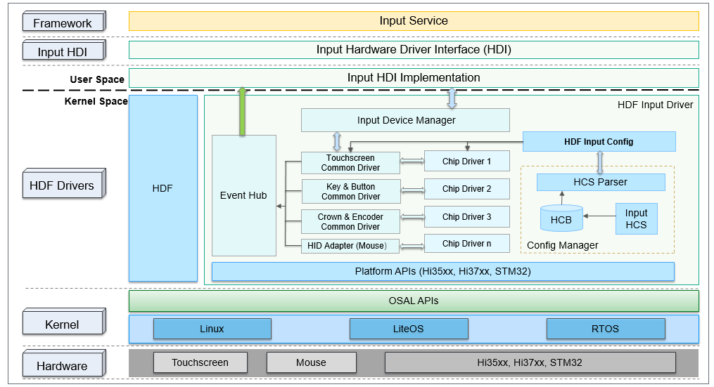
The input driver model consists of the following:
- Input Device Manager: provides APIs for input device drivers to register and deregister input devices and manages the input device list in a unified manner.
- Common input drivers: provide common APIs that are applicable to different input devices (such as the common driver APIs for touchscreens). The APIs can be used to initialize board-specific hardware, handle hardware interrupts, and register input devices with the Input Device Manager.
- Input chip drivers: provide differentiated APIs for the drivers form different vendors. You can use these APIs to develop your drivers with minimum modification.
- Event Hub: provides a unified channel for different input devices to report input events.
- HDF input config: parses and manages the board-specific and private configuration of input devices.
The input driver model provides configuration files to help you quickly develop your drivers.
How to Develop
When to Use
The input module provides APIs for powering on the touchscreen driver IC, configuring and initializing hardware pins, registering interrupts, configuring the communication (I2C or SPI) interface, setting input configurations, and downloading and updating firmware.
Available APIs
Hardware Interfaces
The hardware interfaces for touchscreens can be classified into the following types based on the pin attributes:
-
Power interfaces
-
I/O control interfaces
-
Communication interfaces
Figure 2 Common touchscreen pins

The interfaces shown in the preceding figure are described as follows:
-
Power interfaces
-
LDO_1P8: 1.8 V digital circuit
-
LDO_3P3: 3.3 V analog circuit
If the touchscreen driver and ICD driver have its own IC, the touchscreen driver IC requires 1.8 V and 3.3 V power supplies. If the touchscreen driver and LCD driver have an integrated IC, you only need to care about the 1.8 V power supply for the touchscreen. The 3.3 V power supply required can be provided by the LCD VSP power (typically 5.5 V) in the driver IC.
-
-
I/O control interfaces
- RESET: pin used to reset the driver IC on the host when the kernel is put into hibernation or waken up.
- INT: interrupt pin, which must be set to the input pull-up state during driver initialization. After detecting an external touch signal, the driver triggers an interrupt by operating the interrupt pin. Then, the driver reads the touch reporting data in an interrupt handler.
-
Communication interfaces
Software Interfaces
The HDI driver APIs provided for the input service can be classified into the input manager module, input reporter module, and input controller module. The following tables describe the available APIs.
- input_manager.h
| API | Description |
|---|---|
| int32_t (*OpenInputDevice)(uint32_t devIndex); | Opens an input device. |
| int32_t (*CloseInputDevice)(uint32_t devIndex); | Closes an input device. |
| int32_t (*GetInputDevice)(uint32_t devIndex, DeviceInfo **devInfo); | Obtains information about an input device. |
| int32_t (*GetInputDeviceList)(uint32_t *devNum, DeviceInfo **devList, uint32_t size); | Obtains the input device list. |
- input_reporter.h
| API | Description |
|---|---|
| int32_t (*RegisterReportCallback)(uint32_t devIndex, InputReportEventCb *callback); | Registers a callback for an input device. |
| int32_t (*UnregisterReportCallback)(uint32_t devIndex); | Unregisters the callback for an input device. |
| void (*ReportEventPkgCallback)(const EventPackage **pkgs, uint32_t count); | Called to report input event data. |
- input_controller.h
| API | Description |
|---|---|
| int32_t (*SetPowerStatus)(uint32_t devIndex, uint32_t status); | Sets the power status. |
| int32_t (*GetPowerStatus)(uint32_t devIndex, uint32_t *status); | Obtains the power status. |
| int32_t (*GetDeviceType)(uint32_t devIndex, uint32_t *deviceType); | Obtains the device type. |
| int32_t (*GetChipInfo)(uint32_t devIndex, char *chipInfo, uint32_t length); | Obtains the chip information of a device. |
| int32_t (*GetVendorName)(uint32_t devIndex, char *vendorName, uint32_t length); | Obtains the module vendor name of a device. |
| int32_t (*GetChipName)(uint32_t devIndex, char *chipName, uint32_t length); | Obtains the driver chip name of a device. |
| int32_t (*SetGestureMode)(uint32_t devIndex, uint32_t gestureMode); | Sets the gesture mode. |
| int32_t (*RunCapacitanceTest)(uint32_t devIndex, uint32_t testType, char *result, uint32_t length); | Performs a capacitance test. |
| int32_t (*RunExtraCommand)(uint32_t devIndex, InputExtraCmd *cmd); | Executes the specified command. |
For more information, see input.
Development Procedure
The load process of the input driver model (for the touchscreen driver) is as follows:
-
The device configuration, including the driver loading priority, board-specific hardware information, and private data, is complete.
-
The HDF driver loads the input device manager driver to create and initialize the device manager.
-
The HDF loads the platform driver to parse the board-specific configuration, initialize the hardware, and provide the API for registering the touchscreen.
-
The HDF loads the touchscreen driver to instantiate the touchscreen device, parse the private data, and implement the differentiated APIs for the platform.
-
The instantiated touchscreen device registers with the platform driver to bind the device and the driver and complete the device initialization, including interrupt registration and device power-on and power-off.
-
The instantiated input device registers with the input device manager for unified management.
The development process of the touchscreen driver is as follows:
-
Configure device information.
The input driver is developed based on the HDF. The HDF loads and starts the driver in a unified manner. You need to configure the driver information, such as whether to load the driver and the loading priority, in the configuration file. Then, the HDF starts the registered driver modules one by one. For details about the driver configuration, see HDF Driver Development Process. -
Configure board-specific information and touchscreen private information.
Configure the I/O pin functions. For example, set registers for the I2C pins on the board for the touchscreen to enable I2C communication. -
Implement device-specific APIs.
Based on the communication interfaces designed for the board, use the pin operation APIs provided by the platform interface layer to configure the corresponding reset pin, interrupt pin, and power operations. For details about GPIO operations, see GPIO.
Development Example
The following example describes how to develop the touchscreen driver for an RK3568 development board.
-
Configure device information.
Configure the modules of the input driver model in vendor/hihope/rk3568/hdf_config/khdf/device_info/device_info.hcs. For details, see HDF Driver Development Process. The HDF loads modules of the input model in sequence based on the configuration information.
input :: host { hostName = "input_host"; priority = 100; device_input_manager :: device { device0 :: deviceNode { policy = 2; // The driver provides services externally. priority = 100; // Loading priority. In the input model, the manager module has the highest priority. preload = 0; // Whether to load the driver. The value 0 means to load the driver; 1 means the opposite. permission = 0660; moduleName = "HDF_INPUT_MANAGER"; serviceName = "input_dev_manager"; deviceMatchAttr = ""; } } device_hdf_touch :: device { device0 :: deviceNode { policy = 2; priority = 120; preload = 0; permission = 0660; moduleName = "HDF_TOUCH"; serviceName = "event1"; deviceMatchAttr = "touch_device1"; } } device_touch_chip :: device { device0 :: deviceNode { policy = 0; priority = 130; preload = 0; permission = 0660; moduleName = "HDF_TOUCH_SAMPLE"; serviceName = "hdf_touch_sample_service"; deviceMatchAttr = "zsj_sample_5p5"; } } } -
Configure board-specific and private data for the touchscreen.
Configure the data in vendor/hihope/rk3568/hdf_config/khdf/input/input_config.hcs. The following is an example. You can modify the configuration as required.
root { input_config { touchConfig { touch0 { boardConfig { match_attr = "touch_device1"; inputAttr { inputType = 0; // 0 indicates touchscreen. solutionX = 480; solutionY = 960; devName = "main_touch"; // Device name. } busConfig { busType = 0; // 0 indicates I2C. busNum = 6; clkGpio = 86; dataGpio = 87; i2cClkIomux = [0x114f0048, 0x403]; // Register of the I2C_CLK pin. i2cDataIomux = [0x114f004c, 0x403]; // Register of the I2C_DATA pin. } pinConfig { rstGpio = 3; intGpio = 4; rstRegCfg = [0x112f0094, 0x400]; // Register of the reset pin. intRegCfg = [0x112f0098, 0x400]; // Register of the interrupt pin. } powerConfig { vccType = 2; // The value 1 stands for LDO, 2 for GPIO, and 3 for PMIC. vccNum = 20; // Set the GPIO number to 20. vccValue = 1800; // Set the voltage amplitude to 1800 mV. vciType = 1; vciNum = 12; vciValue = 3300; } featureConfig { capacitanceTest = 0; gestureMode = 0; gloverMOde = 0; coverMode = 0; chargerMode = 0; knuckleMode = 0; } } chipConfig { template touchChip { match_attr = ""; chipName = "sample"; vendorName = "zsj"; chipInfo = "AAAA11222"; // The first four characters indicate the product name. The fifth and sixth characters indicate the IC model. The last three characters indicate the model number. busType = 0; deviceAddr = 0x5D; irqFlag = 2; // The value 1 means to trigger an interrupt on the rising edge, 2 means to trigger an interrupt on the falling edge, 4 means to trigger an interrupt by the high level, and 8 means to trigger an interrupt by the low level. maxSpeed = 400; chipVersion = 0; powerSequence { /* Description of the power-on sequence: [type, status, direction, delay] <type> 0 stands for null; 1 for VCC power (1.8 V); 2 for VCI power (3.3 V); 3 for reset pin; 4 for interrupt pin. <status> 0 stands for power-off or pull-down; 1 for power-on or pull-up; 2 for no operation. <dir> 0 stands for input; 1 for output; 2 for no operation. <delay> indicates the delay, in milliseconds. For example, 20 indicates 20 ms delay. */ powerOnSeq = [4, 0, 1, 0, 3, 0, 1, 10, 3, 1, 2, 60, 4, 2, 0, 0]; suspendSeq = [3, 0, 2, 10]; resumeSeq = [3, 1, 2, 10]; powerOffSeq = [3, 0, 2, 10, 1, 0, 2, 20]; } } chip0 :: touchChip { match_attr = "zsj_sample_5p5"; chipInfo = "ZIDN45100"; chipVersion = 0; } } } } } } -
Add the touchscreen driver.
Implement the touchscreen-specific APIs in drivers/hdf_core/framework/model/input/driver/touchscreen/touch_gt911.c.
The following uses the APIs for obtaining and parsing device data as an example. You can implement the related APIs to match your development.
/* Parse the touch reporting data read from the touchscreen into coordinates. */ static void ParsePointData(ChipDevice *device, FrameData *frame, uint8_t *buf, uint8_t pointNum) { int32_t resX = device->driver->boardCfg->attr.resolutionX; int32_t resY = device->driver->boardCfg->attr.resolutionY; for (int32_t i = 0; i < pointNum; i++) { frame->fingers[i].y = (buf[GT_POINT_SIZE * i + GT_X_LOW] & ONE_BYTE_MASK) | ((buf[GT_POINT_SIZE * i + GT_X_HIGH] & ONE_BYTE_MASK) << ONE_BYTE_OFFSET); frame->fingers[i].x = (buf[GT_POINT_SIZE * i + GT_Y_LOW] & ONE_BYTE_MASK) | ((buf[GT_POINT_SIZE * i + GT_Y_HIGH] & ONE_BYTE_MASK) << ONE_BYTE_OFFSET); frame->fingers[i].valid = true; } } /* Obtain the touch reporting data from the device. */ static int32_t ChipDataHandle(ChipDevice *device) { int32_t ret; uint8_t touchStatus = 0; uint8_t pointNum; uint8_t buf[GT_POINT_SIZE * MAX_SUPPORT_POINT] = {0}; InputI2cClient *i2cClient = &device->driver->i2cClient; uint8_t reg[GT_ADDR_LEN] = {0}; FrameData *frame = &device->driver->frameData; reg[0] = (GT_BUF_STATE_ADDR >> ONE_BYTE_OFFSET) & ONE_BYTE_MASK; reg[1] = GT_BUF_STATE_ADDR & ONE_BYTE_MASK; ret = InputI2cRead(i2cClient, reg, GT_ADDR_LEN, &touchStatus, 1); if (ret < 0 || touchStatus == GT_EVENT_INVALID) { return HDF_FAILURE; } OsalMutexLock(&device->driver->mutex); (void)memset_s(frame, sizeof(FrameData), 0, sizeof(FrameData)); if (touchStatus == GT_EVENT_UP) { frame->realPointNum = 0; frame->definedEvent = TOUCH_UP; goto exit; } reg[0] = (GT_X_LOW_BYTE_BASE >> ONE_BYTE_OFFSET) & ONE_BYTE_MASK; reg[1] = GT_X_LOW_BYTE_BASE & ONE_BYTE_MASK; pointNum = touchStatus & GT_FINGER_NUM_MASK; if (pointNum <= 0 || pointNum > MAX_SUPPORT_POINT) { HDF_LOGE("%s: pointNum is invalid, %d", __func__, pointNum); (void)ChipCleanBuffer(i2cClient); OsalMutexUnlock(&device->driver->mutex); return HDF_FAILURE; } frame->realPointNum = pointNum; frame->definedEvent = TOUCH_DOWN; /* Read the touch reporting data from the register. */ (void)InputI2cRead(i2cClient, reg, GT_ADDR_LEN, buf, GT_POINT_SIZE * pointNum); /* Parse the touch reporting data. */ ParsePointData(device, frame, buf, pointNum); exit: OsalMutexUnlock(&device->driver->mutex); if (ChipCleanBuffer(i2cClient) != HDF_SUCCESS) { return HDF_FAILURE; } return HDF_SUCCESS; } static struct TouchChipOps g_sampleChipOps = { .Init = ChipInit, .Detect = ChipDetect, .Resume = ChipResume, .Suspend = ChipSuspend, .DataHandle = ChipDataHandle, }; static TouchChipCfg *ChipConfigInstance(struct HdfDeviceObject *device) { TouchChipCfg *chipCfg = (TouchChipCfg *)OsalMemAlloc(sizeof(TouchChipCfg)); if (chipCfg == NULL) { HDF_LOGE("%s: instance chip config failed", __func__); return NULL; } (void)memset_s(chipCfg, sizeof(TouchChipCfg), 0, sizeof(TouchChipCfg)); /* Parse the touchscreen private configuration. */ if (ParseTouchChipConfig(device->property, chipCfg) != HDF_SUCCESS) { HDF_LOGE("%s: parse chip config failed", __func__); OsalMemFree(chipCfg); chipCfg = NULL; } return chipCfg; } static ChipDevice *ChipDeviceInstance(void) { ChipDevice *chipDev = (ChipDevice *)OsalMemAlloc(sizeof(ChipDevice)); if (chipDev == NULL) { HDF_LOGE("%s: instance chip device failed", __func__); return NULL; } (void)memset_s(chipDev, sizeof(ChipDevice), 0, sizeof(ChipDevice)); return chipDev; } static void FreeChipConfig(TouchChipCfg *config) { if (config->pwrSeq.pwrOn.buf != NULL) { OsalMemFree(config->pwrSeq.pwrOn.buf); } if (config->pwrSeq.pwrOff.buf != NULL) { OsalMemFree(config->pwrSeq.pwrOff.buf); } OsalMemFree(config); } static int32_t HdfSampleChipInit(struct HdfDeviceObject *device) { TouchChipCfg *chipCfg = NULL; ChipDevice *chipDev = NULL; HDF_LOGE("%s: enter", __func__); if (device == NULL) { return HDF_ERR_INVALID_PARAM; } /* Parse the touchscreen private configuration. */ chipCfg = ChipConfigInstance(device); if (chipCfg == NULL) { return HDF_ERR_MALLOC_FAIL; } /* Instantiate the touchscreen device. */ chipDev = ChipDeviceInstance(); if (chipDev == NULL) { goto freeCfg; } chipDev->chipCfg = chipCfg; chipDev->ops = &g_sampleChipOps; chipDev->chipName = chipCfg->chipName; chipDev->vendorName = chipCfg->vendorName; /* Register the touchscreen device with the platform driver. */ if (RegisterChipDevice(chipDev) != HDF_SUCCESS) { goto freeDev; } HDF_LOGI("%s: exit succ, chipName = %s", __func__, chipCfg->chipName); return HDF_SUCCESS; freeDev: OsalMemFree(chipDev); freeCfg: FreeChipConfig(chipCfg); return HDF_FAILURE; } struct HdfDriverEntry g_touchSampleChipEntry = { .moduleVersion = 1, .moduleName = "HDF_TOUCH_SAMPLE", .Init = HdfSampleChipInit, }; HDF_INIT(g_touchSampleChipEntry); -
Call the Input HDI APIs.
The following sample code shows how an upper-layer input system service calls Input HDI APIs.
#include "input_manager.h"
#define DEV_INDEX 1

IInputInterface *g_inputInterface;
InputReportEventCb g_callback;

/* Define the callback for data reporting. */
static void ReportEventPkgCallback(const EventPackage **pkgs, uint32_t count)
{
    if (pkgs == NULL || count > MAX_PKG_NUM) {
        return;
    }
    for (uint32_t i = 0; i < count; i++) {
        HDF_LOGI("%s: pkgs[%d] = 0x%x, 0x%x, %d", __func__, i, pkgs[i]->type, pkgs[i]->code, pkgs[i]->value);
    }
}

int InputServiceSample(void)
{
    uint32_t devType = INIT_DEFAULT_VALUE;

    /* Obtain the input driver APIs. */
    int ret = GetInputInterface(&g_inputInterface);
    if (ret != INPUT_SUCCESS) {
        HDF_LOGE("%s: get input interfaces failed, ret = %d", __func__, ret);
        return ret;
    }

    INPUT_CHECK_NULL_POINTER(g_inputInterface, INPUT_NULL_PTR);
    INPUT_CHECK_NULL_POINTER(g_inputInterface->iInputManager, INPUT_NULL_PTR);
    /* Open an input device. */
    ret = g_inputInterface->iInputManager->OpenInputDevice(DEV_INDEX);
    if (ret) {
        HDF_LOGE("%s: open input device failed, ret = %d", __func__, ret);
      return ret;
    }

    INPUT_CHECK_NULL_POINTER(g_inputInterface->iInputController, INPUT_NULL_PTR);
    /* Obtain the type of the input device. */
    ret = g_inputInterface->iInputController->GetDeviceType(DEV_INDEX, &devType);
    if (ret) {
        HDF_LOGE("%s: get device type failed, ret: %d", __FUNCTION__, ret);
        return ret;
    }
    HDF_LOGI("%s: device1's type is %u\n", __FUNCTION__, devType);

    /* Register the data reporting callback for the input device. */
    g_callback.ReportEventPkgCallback = ReportEventPkgCallback;
    INPUT_CHECK_NULL_POINTER(g_inputInterface->iInputReporter, INPUT_NULL_PTR);
    ret  = g_inputInterface->iInputReporter->RegisterReportCallback(DEV_INDEX, &g_callback);
    if (ret) {
        HDF_LOGE("%s: register callback failed, ret: %d", __FUNCTION__, ret);
      return ret;
    }
    HDF_LOGI("%s: wait 10s for testing, pls touch the panel now", __FUNCTION__);
    OsalMSleep(KEEP_ALIVE_TIME_MS);

    /* Unregister the callback for the input device. */
    ret = g_inputInterface->iInputReporter->UnregisterReportCallback(DEV_INDEX);
    if (ret) {
        HDF_LOGE("%s: unregister callback failed, ret: %d", __FUNCTION__, ret);
        return ret;
    }

    /* Close the input device. */
    ret = g_inputInterface->iInputManager->CloseInputDevice(DEV_INDEX);
    if (ret) {
        HDF_LOGE("%s: close device failed, ret: %d", __FUNCTION__, ret);
      return ret;
    }
    return 0;
}