I3C
Introduction
Function
Improved Inter-Integrated Circuit (I3C) is a simple and cost-efficient two-wire bidirectional synchronous serial bus protocol developed by the Mobile Industry Processor Interface (MIPI) Alliance.
I3C is a two-wire bidirectional serial bus, optimized for multiple sensor target devices and controlled by only one I3C controller at a time. It is backward compatible with Inter-Integrated circuit (I2C) target devices, but features higher speed and lower power consumption and supports in-band interrupts (IBIs), hot-joins of target devices, and controller switchover.
The IBIs over the serial bus eliminates the need for an extra interrupt line to complete interrupts in I2C. I2C devices, I3C target devices, and the I3C secondary controller can co-exist on the same I3C bus.
Basic Concepts
-
IBI
When there is no start signal on the serial clock (SCL) line, the I3C target device can pull down the serial data (SDA) line to make the controller send an SCL start signal, which initiates an IBI request. If multiple target devices send interrupt requests at the same time, the I3C controller arbitrates the requests based on the target device addresses. The request with a lower address is responded first.
-
Dynamic Address Assignment (DAA)
The I3C controller can dynamically allocate addresses to target devices to avoid address conflicts. Before addresses are allocated, each I3C device connected to an I3C bus must be uniquely identified in either of the following ways:
- The device has an I2C compliant static address that can be used by the host.
- The device has a 48-bit temporary ID.
The host must use a 48-bit temporary ID unless the device has a static IP address.
-
Common Command Code (CCC)
All I3C devices support CCC. The CCC can be sent to an I3C target device or all I3C target devices.
-
Bus Characteristic Register (BCR)
Each I3C device connected to an I3C bus has a read-only BCR, which describes the I3C compliant device's role and capabilities for use in DAA and CCC.
-
Device Characteristic Register (DCR)
Each I3C device connected to an I3C bus has a read-only DCR, which describes the I3C compliant device type (such as accelerometers, gyroscope, and others) for use in DAA and DCC.
Working Principles
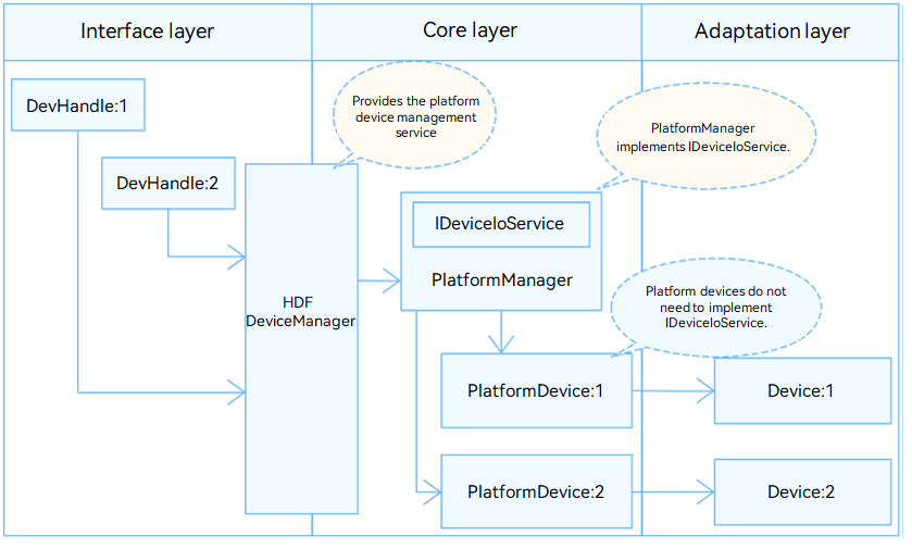
In the Hardware Driver Foundation (HDF), the I3C module uses the unified service mode for API adaptation. In this mode, a service is used as the I3C manager to handle external access requests in a unified manner. The unified service mode applies when the system has multiple device objects of the same type, for example, when there are more than 10 I3C controllers. If the independent service mode is used in this case, more device nodes need to be configured and more memory resources will be consumed. The following figure illustrtes the unified service mode.
The I3C module is divided into the following layers:
- Interface layer: provides the capabilities of opening a device, writing data, and closing a device.
- Core layer: binds services, initializes and releases the PlatformManager, and provides the capabilities of adding, deleting, and obtaining controllers. The core layer also provides capabilities of adding, deleting, and obtaining the devices connected to the I3C bus and interrupt callbacks.
- Adaptation layer: implements hardware-related functions, such as controller initialization.
In the unified service mode, the core layer manages all controllers in a unified manner and publishes a service for the interface layer. That is, the driver does not need to publish a service for each controller.
Figure 1 Unified service mode
Constraints
The I3C module supports only the kernel (LiteOS-A) for mini and small systems.
Development Guidelines
When to Use
I3C can connect to one or more I3C or I2C target devices. It is used to:
- Communicate with sensors, such as gyroscopes, barometers, and image sensors that support the I3C protocol.
- Communicate with devices with other ports (such as UART serial ports) through software or hardware protocols.
Before using I3C devices with OpenHarmony, you need to adapt the I3C driver to OpenHarmony. The following describes how to do it.
Available APIs
To enable the upper layer to successfully operate the hardware by calling the I3C APIs, hook functions are defined in //drivers/hdf_core/framework/support/platform/include/i3c/i3c_core.h for the core layer. You need to implement these hook functions at the adaptation layer and hook them to implement the interaction between the interface layer and the core layer.
I3cMethod:
struct I3cMethod {
    int32_t (*sendCccCmd)(struct I3cCntlr *cntlr, struct I3cCccCmd *ccc);
    int32_t (*transfer)(struct I3cCntlr *cntlr, struct I3cMsg *msgs, int16_t count);
    int32_t (*i2cTransfer)(struct I3cCntlr *cntlr, struct I3cMsg *msgs, int16_t count);
    int32_t (*setConfig)(struct I3cCntlr *cntlr, struct I3cConfig *config);
    int32_t (*getConfig)(struct I3cCntlr *cntlr, struct I3cConfig *config);
    int32_t (*requestIbi)(struct I3cDevice *dev);
    void (*freeIbi)(struct I3cDevice *dev);
};
Table 1 Hook functions in I3cMethod
| Function | Input Parameter | Output Parameter | Return Value | Description |
|---|---|---|---|---|
| sendCccCmd | cntlr: structure pointer to an I3C controller at the core layer. ccc: pointer to the CCC to send. |
ccc: pointer to the CCC sent. | HDF_STATUS | Sends a CCC. |
| Transfer | cntlr: structure pointer to an I3C controller at the core layer. msgs: structure pointer to the messages to transfer. count: number of messages to transfer, which is of the int16_t type. |
msgs: structure pointer to the messages transferred. | HDF_STATUS | Transfers user messages in I3C mode. |
| i2cTransfer | cntlr: structure pointer to an I3C controller at the core layer. msgs: structure pointer to the messages to transfer. count: number of messages to transfer, which is of the int16_t type. |
msgs: structure pointer to the messages transferred. | HDF_STATUS | Transfers user messages in I2C mode. |
| setConfig | cntlr: structure pointer to an I3C controller at the core layer. config: pointer to the controller configuration. |
– | HDF_STATUS | Sets an I3C controller. |
| getConfig | cntlr: structure pointer to an I3C controller at the core layer. | config: pointer to the controller configuration. | HDF_STATUS | Obtains the I3C controller configuration. |
| requestIbi | device: structure pointer to an I3C device at the core layer. | – | HDF_STATUS | Requests an IBI for an I3C device. |
| freeIbi | device: structure pointer to an I3C device at the core layer. | – | HDF_STATUS | Releases the IBI for an I3C device. |
How to Develop
The I3C module adaptation involves the following steps:
-
Instantiate the driver entry.
- Instantiate the HdfDriverEntry structure.
- Call HDF_INIT to register the HdfDriverEntry instance with the HDF.
-
Configure attribute files.
- Add the deviceNode information to the device_info.hcs file.
- (Optional) Add the i3c_config.hcs file.
-
Instantiate the I3C controller object.
- Initialize I3cCntlr.
- Instantiate I3cMethod in I3cCntlr. For details, see the description of I3cMethod below.
-
Register an interrupt handler.
Registers an interrupt handler for the controller to implement the device hot-join and IBI features.
Example
-
Instantiate the driver entry.
The driver entry must be a global variable of the HdfDriverEntry type (defined in //drivers/hdf_core/framework/include/core/hdf_device_desc.h), and the module name must be the same as that in device_info.hcs. In the HDF, the start address of each HdfDriverEntry object of all loaded drivers is collected to form a segment address space similar to an array for the upper layer to invoke.
Generally, the HDF calls the Bind function and then the Init function to load a driver. If Init fails to be called, the HDF calls Release to release driver resources and exit.
I3C driver entry example:
 NOTE
NOTEMultiple devices may connect to the I3C controller. In the HDF, a manager object needs to be created for this type of devices, and a manager service is published to handle external access requests uniformly. When a device needs to be started, the manager service locates the target device based on the specified parameters.
You do not need to implement the driver of the I3C manager, which is implemented by the core layer. However, the I3cCntlrAdd function of the core layer must be invoked in the Init function to implement the related features.
static struct HdfDriverEntry g_virtualI3cDriverEntry = { .moduleVersion = 1, .Init = VirtualI3cInit, .Release = VirtualI3cRelease, .moduleName = "virtual_i3c_driver", // (Mandatory) The value must be the same as that in the .hcs file. }; HDF_INIT(g_virtualI3cDriverEntry); // Call HDF_INIT to register the driver entry with the HDF. /* Driver entry of the i3c_core.c manager service at the core layer. */ struct HdfDriverEntry g_i3cManagerEntry = { .moduleVersion = 1, .Init = I3cManagerInit, .Release = I3cManagerRelease, .moduleName = "HDF_PLATFORM_I3C_MANAGER", // The value must be the same as that of device0 in the device_info.hcs file. }; HDF_INIT(g_i3cManagerEntry); -
Configure attribute files.
Add the deviceNode information to the //vendor/hisilicon/hispark_taurus/hdf_config/device_info/device_info.hcs file and configure the device attributes in i3c_config.hcs.
The deviceNode information is related to the driver entry registration. The device attribute values are closely related to the driver implementation and the default values or value ranges of the I3cCntlr members at the core layer.
In the unified service mode, the first device node in the device_info.hcs file must be the I3C manager. The I3C manager parameters must be set as follows:
| Parameter | Value |
|---|---|
| moduleName | HDF_PLATFORM_I3C_MANAGER |
| serviceName | Reserved. |
| policy | 0 |
| cntlrMatchAttr | Reserved. |
Configure I3C controller information from the second node. This node specifies a type of I3C controllers rather than a specific I3C controller. In this example, there is only one I3C controller. If there are multiple I3C controllers, add the **deviceNode** information to the **device_info.hcs** file and add the corresponding device attributes to the **i3c_config** file for each controller.

- **device_info.hcs** example

    ```c
    root {
        device_i3c :: device {
            device0 :: deviceNode {
                policy = 0;
                priority = 52;
                permission = 0644;
                serviceName = "HDF_PLATFORM_I3C_MANAGER";
                moduleName = "HDF_PLATFORM_I3C_MANAGER";
            }
        }
        i3c_virtual :: deviceNode {
            policy = 0;                               // The value 0 indicates that no service is published.
            priority = 56;                            // Driver startup priority.
            permission = 0644;                        // Permission for the device node created.
            moduleName = "virtual_i3c_driver";        // (Mandatory) Driver name, which must be the same as moduleName in the driver entry.
            serviceName = "VIRTUAL_I3C_DRIVER";       // (Mandatory) Unique name of the service published by the driver.
            deviceMatchAttr = "virtual_i3c"; // (Mandatory) Controller private data, which must be same as that of the controller in i3c_config.hcs.
        }                                             // The specific controller information is in i3c_config.hcs.
    }
    ```

- i3c_config.hcs example

    ```c
    root {
        platform {
            i3c_config {
                match_attr = "virtual_i3c";  // (Mandatory) The value must be the same as that of deviceMatchAttr in device_info.hcs.
                template i3c_controller {    // Template configuration. In the template, you can configure the common parameters shared by device nodes.
                    busId = 0;               // (Mandatory) I3C bus number.
                    busMode = 0x0;           // Bus mode, which can be 0x0 (pure), 0x1 (mixed-fast), 0x2 (mixed-limited), or 0x3 (mixed-slow).
                    regBasePhy = 0x120b0000; // (Mandatory) Physical base address.
                    regSize = 0xd1;          // (Mandatory) Register bit width.
                    IrqNum = 20;             // (Mandatory) Interrupt request (IRQ) number.
                    i3cMaxRate = 12900000;   // (Optional) Maximum clock rate in I3C mode.
                    i3cRate = 12500000;      // (Optional) Clock rate in I3C mode.
                    i2cFmRate = 1000000;     // (Optional) Clock rate in I2C FM mode.
                    i2cFmPlusRate = 400000;  // (Optional) Clock rate in I2C FM+ mode.
                }
                controller_0 :: i3c_controller {
                    busId = 18;
                    IrqNum = 20;
                }
            }
        }
    }
    ```
    After the **i3c_config.hcs** file is configured, include the file in the **hdf.hcs** file. Otherwise, the configuration file cannot take effect.

     For example, if the path of **i3c_config.hcs** is **device/soc/hisilicon/hi3516dv300/sdk_liteos/hdf_config/i3c/i3c_config.hcs**, add the following statement to **hdf.hcs** of the product:

    ```c
     #include "../../../../device/soc/hisilicon/hi3516dv300/sdk_liteos/hdf_config/i3c/i3c_config.hcs" // Relative path of the file.
    ```
-
Instantiate the I3C controller object.
Initialize the I3cCntlr object at the core layer, including defining a custom structure (to pass parameters and data) and implementing the HdfDriverEntry member functions (Bind, Init, and Release) to instantiate I3cMethod in I3cCntlr (so that the underlying driver functions can be called).
Instantiate I3cMethod in I3cCntlr.
The I3cLockMethod hook function structure is not implemented in this example. To instantiate the structure, refer to the I2C driver development. Other members are initialized in Init().-
Define a custom structure.
NOTETo the driver, the custom structure holds parameters and data. The DeviceResourceIface method provided by the HDF reads the values in the i3c_config.hcs file to initialize the members in the custom structure and passes important parameters, such as the device number and bus number, to the I3cCntlr object at the core layer.
struct VirtualI3cCntlr { struct I3cCntlr cntlr; // (Mandatory) Control object at the core layer. For details, see the following description. volatile unsigned char *regBase; // (Mandatory) Register base address. uint32_t regBasePhy // (Mandatory) Physical base address of the register. uint32_t regSize; // (Mandatory) Register bit width. uint16_t busId; // (Mandatory) Bus number. uint16_t busMode; uint16_t IrqNum; uint32_t i3cMaxRate; uint32_t i3cRate; uint32_t i2cFmRate; uint32_t i2cFmPlusRate; }; /* I3cCntlr is the controller structure at the core layer. The Init function assigns values to the members of I3cCntlr. */ struct I3cCntlr { OsalSpinlock lock; void *owner; int16_t busId; struct I3cConfig config; uint16_t addrSlot[(I3C_ADDR_MAX + 1) / ADDRS_PER_UINT16]; struct I3cIbiInfo *ibiSlot[I3C_IBI_MAX]; const struct I3cMethod *ops; const struct I3cLockMethod *lockOps; void *priv; }; -
Implement the Init function.
Input parameter:
HdfDeviceObject, an interface parameter provided by the driver, contains the .hcs information.
Return value:
HDF_STATUS
The table below describes some status. For more information, see HDF_STATUS in the //drivers/hdf_core/framework/include/utils/hdf_base.h file.
-
| Status | Description |
|---|---|
| HDF_ERR_INVALID_OBJECT | Invalid controller object. |
| HDF_ERR_INVALID_PARAM | Invalid parameter. |
| HDF_ERR_MALLOC_FAIL | Failed to allocate the memory. |
| HDF_ERR_IO | I/O error. |
| HDF_SUCCESS | Transmission successful. |
| HDF_FAILURE | Transmission failed. |
**Function description**:
Initializes the custom structure object and **I3cCntlr**, and calls the **I3cCntlrAdd** function to add the I3C controller to the core layer.
```c
static int32_t VirtualI3cParseAndInit(struct HdfDeviceObject *device, const struct DeviceResourceNode *node)
{
int32_t ret;
struct VirtualI3cCntlr *virtual = NULL; // (Mandatory) Custom structure object.
(void)device;
virtual = (struct VirtualI3cCntlr *)OsalMemCalloc(sizeof(*virtual)); // (Mandatory) Allocate memory.
if (virtual == NULL) {
HDF_LOGE("%s: Malloc virtual fail!", __func__);
return HDF_ERR_MALLOC_FAIL;
}
ret = VirtualI3cReadDrs(virtual, node); // (Mandatory) Use the default values in the i3c_config file to fill in the structure. For details about the function definition, see the following.
if (ret != HDF_SUCCESS) {
HDF_LOGE("%s: Read drs fail! ret:%d", __func__, ret);
goto __ERR__;
}
...
virtual->regBase = OsalIoRemap(virtual->regBasePhy, virtual->regSize);// (Mandatory) Address mapping.
ret = OsalRegisterIrq(hi35xx->softIrqNum, OSAL_IRQF_TRIGGER_NONE, I3cIbiHandle, "I3C", virtual); // (Mandatory) Register an interrupt handler.
if (ret != HDF_SUCCESS) {
HDF_LOGE("%s: register irq failed!", __func__);
return ret;
}
...
VirtualI3cCntlrInit(virtual); // (Mandatory) Initialize the I3C device.
virtual->cntlr.priv = (void *)node; // (Mandatory) Set the storage device attributes.
virtual->cntlr.busId = virtual->busId; // (Mandatory) Initialize I3cCntlr.
virtual->cntlr.ops = &g_method; // (Mandatory) Attach the I3cMethod instance.
(void)OsalSpinInit(&virtual->spin);
ret = I3cCntlrAdd(&virtual->cntlr); // (Mandatory) Call this function to add the controller to the core layer. The driver can access the platform core layer only when a success signal is returned.
if (ret != HDF_SUCCESS) {
HDF_LOGE("%s: add i3c controller failed! ret = %d", __func__, ret);
(void)OsalSpinDestroy(&virtual->spin);
goto __ERR__;
}
return HDF_SUCCESS;
__ERR__: // If the controller fails to be added, deinitialize related functions.
if (virtual != NULL) {
OsalMemFree(virtual);
virtual = NULL;
}
return ret;
}
static int32_t VirtualI3cInit(struct HdfDeviceObject *device)
{
int32_t ret;
const struct DeviceResourceNode *childNode = NULL;
if (device == NULL || device->property == NULL) {
HDF_LOGE("%s: device or property is NULL", __func__);
return HDF_ERR_INVALID_OBJECT;
}
DEV_RES_NODE_FOR_EACH_CHILD_NODE(device->property, childNode) {
ret = VirtualI3cParseAndInit(device, childNode);
if (ret != HDF_SUCCESS) {
break;
}
}
return ret;
}
static int32_t VirtualI3cReadDrs(struct VirtualI3cCntlr *virtual, const struct DeviceResourceNode *node)
{
struct DeviceResourceIface *drsOps = NULL;
/* Obtain the drsOps method. */
drsOps = DeviceResourceGetIfaceInstance(HDF_CONFIG_SOURCE);
if (drsOps == NULL || drsOps->GetUint32 == NULL || drsOps->GetUint16 == NULL) {
HDF_LOGE("%s: Invalid drs ops fail!", __func__);
return HDF_FAILURE;
}
/* Read the configuration parameters in sequence and fill them in the structure. */
if (drsOps->GetUint16(node, "busId", &virtual->busId, 0) != HDF_SUCCESS) {
HDF_LOGE("%s: Read busId fail!", __func__);
return HDF_ERR_IO;
}
if (drsOps->GetUint16(node, "busMode", &virtual->busMode, 0) != HDF_SUCCESS) {
HDF_LOGE("%s: Read busMode fail!", __func__);
return HDF_ERR_IO;
}
if (drsOps->GetUint16(node, "IrqNum", &virtual->IrqNum, 0) != HDF_SUCCESS) {
HDF_LOGE("%s: Read IrqNum fail!", __func__);
return HDF_ERR_IO;
}
···
return HDF_SUCCESS;
}
```
- Implement the **Release** function.
**Input parameter**:
**HdfDeviceObject**, an interface parameter provided by the driver, contains the .hcs information.
**Return value**:
No value is returned.
**Function description**:
Releases the memory and deletes the controller. This function assigns values to the **Release** function in the driver entry structure. If the HDF fails to call the **Init** function to initialize the driver, the **Release** function can be called to release driver resources.
>  **NOTE**
>
> All forced conversion operations for obtaining the corresponding object can be successful only when the **Init** function has the value assignment operations.
```c
static void VirtualI3cRemoveByNode(const struct DeviceResourceNode *node)
{
int32_t ret;
int16_t busId;
struct I3cCntlr *cntlr = NULL;
struct VirtualI3cCntlr *virtual = NULL;
struct DeviceResourceIface *drsOps = NULL;
drsOps = DeviceResourceGetIfaceInstance(HDF_CONFIG_SOURCE);
if (drsOps == NULL || drsOps->GetUint32 == NULL) {
HDF_LOGE("%s: invalid drs ops fail!", __func__);
return;
}
ret = drsOps->GetUint16(node, "busId", (uint16_t *)&busId, 0);
if (ret != HDF_SUCCESS) {
HDF_LOGE("%s: read busId fail!", __func__);
return;
}
...
/* Call I3cCntlrGet() to obtain the I3cCntlr object based on the cntlrNum of the device, and then call I3cCntlrRemove() to release the I3cCntlr object. */
cntlr = I3cCntlrGet(busId);
if (cntlr != NULL && cntlr->priv == node) {
I3cCntlrPut(cntlr);
I3cCntlrRemove(cntlr); // (Mandatory) Remove the I3cCntlr object from the manager driver.
virtual = (struct VirtualI3cCntlr *)cntlr; // (Mandatory) Obtain the custom object through a forced conversion and perform the release operation.
(void)OsalSpinDestroy(&virtual->spin);
OsalMemFree(virtual);
}
return;
}
static void VirtualI3cRelease(struct HdfDeviceObject *device)
{
const struct DeviceResourceNode *childNode = NULL;
HDF_LOGI("%s: enter", __func__);
if (device == NULL || device->property == NULL) {
HDF_LOGE("%s: device or property is NULL", __func__);
return;
}
...
/* Traverse and parse all nodes in i3c_config.hcs and perform the release operation on each node. */
DEV_RES_NODE_FOR_EACH_CHILD_NODE(device->property, childNode) {
VirtualI3cRemoveByNode(childNode); // See the description of VirtualI3cRemoveByNode for more details.
}
}
```
-
Register an interrupt handler.
The interrupt handler performs an IBI or hot-join based on the address where the interrupt is generated.
static int32_t VirtualI3cReservedAddrWorker(struct VirtualI3cCntlr *virtual, uint16_t addr)
{
    (void)virtual;
    switch (addr) {
        case I3C_HOT_JOIN_ADDR:
             VirtualI3cHotJoin(virtual);
            break;
        case I3C_RESERVED_ADDR_7H3E:
        case I3C_RESERVED_ADDR_7H5E:
        case I3C_RESERVED_ADDR_7H6E:
        case I3C_RESERVED_ADDR_7H76:
        case I3C_RESERVED_ADDR_7H7A:
        case I3C_RESERVED_ADDR_7H7C:
        case I3C_RESERVED_ADDR_7H7F:
        /* All single-bit errors in the broadcast address */
        HDF_LOGW("%s: broadcast Address single bit error!", __func__);
            break;
        default:
            HDF_LOGD("%s: Reserved address which is not supported!", __func__);
            break;
    }

    return HDF_SUCCESS;
}

static int32_t I3cIbiHandle(uint32_t irq, void *data)
{
    struct VirtualI3cCntlr *virtual = NULL;
    struct I3cDevice *device = NULL;
    uint16_t ibiAddr;
    char *testStr = "Hello I3C!";

    (void)irq;
    if (data == NULL) {
        HDF_LOGW("%s: data is NULL!", __func__);
        return HDF_ERR_INVALID_PARAM;
    }
    virtual = (struct VirtualI3cCntlr *)data;
    /* (Mandatory) Obtain the address where the interrupt is generated. Use the CHECK_RESERVED_ADDR macro to determine whether the address is an I3C address. */
    ibiAddr = VirtualI3cGetIbiAddr();
    if (CHECK_RESERVED_ADDR(ibiAddr) == I3C_ADDR_RESERVED) {
        HDF_LOGD("%s: Calling VirtualI3cResAddrWorker...", __func__);
        return VirtualI3cReservedAddrWorker(virtual, ibiAddr);
    } else {
        HDF_LOGD("%s: Calling I3cCntlrIbiCallback...", __func__);
        device = GetDeviceByAddr(&virtual->cntlr, ibiAddr);
        if (device == NULL) {
            HDF_LOGE("func:%s device is NULL!",__func__);
            return HDF_ERR_MALLOC_FAIL;
        }
        if (device->ibi->payload > VIRTUAL_I3C_TEST_STR_LEN) {
            /* Place the string "Hello I3C!" into the IBI buffer. */
            *device->ibi->data = *testStr;
        }
        /* Invoke the IBI callback based on the I3C device that generates the IBI. */
        return I3cCntlrIbiCallback(device);
    }

    return HDF_SUCCESS;
}