Regulator
Overview
Regulator
The regulator module controls the voltage and current supplies of some devices in the system. In an embedded system (especially a mobile phone), it is important to control the power consumption, which directly affects the battery endurance. You can use a regulator to shut down the power supply to an idle module in the system or reduce the voltage and current for the module.
Working Principles
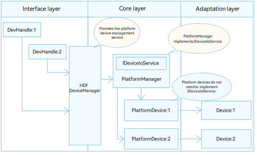
In the Hardware Driver Foundation (HDF), the regulator module uses the unified service mode for API adaptation. In this mode, a device service is used as the regulator manager to handle external access requests in a unified manner, which is reflected in the configuration file. The unified service mode applies when there are many device objects of the same type, for example, when the regulator has more than 10 controllers. If the independent service mode is used, more device nodes need to be configured and more memory resources will be consumed by services.
The regulator module is divided into the following layers:
- Interface layer: provides APIs for opening or closing a device and writing data.
- Core layer: provides the capabilities of binding, initializing, and releasing devices.
- Adaptation layer: implements other functions.
![]() NOTE
NOTE
The core layer can call the APIs of the interface layer and uses hooks to call APIs of the adaptation layer. In this way, the adaptation layer can indirectly call the APIs of the interface layer, but the interface layer cannot call the APIs of the adaptation layer.
Figure 1 Unified service mode
Constraints
Currently, the regulator module supports only the kernels (LiteOS) of mini and small systems.
Development Guidelines
When to Use
The regulator module controls the voltage and current supplies of some devices in the system.
Available APIs
The functions in RegulatorMethod are used to call the corresponding regulator driver functions:
RegulatorMethod structure:
struct RegulatorMethod {
    int32_t (*open)(struct RegulatorNode *node);
    int32_t (*close)(struct RegulatorNode *node);
    int32_t (*release)(struct RegulatorNode *node);
    int32_t (*enable)(struct RegulatorNode *node);
    int32_t (*disable)(struct RegulatorNode *node);
    int32_t (*forceDisable)(struct RegulatorNode *node);
    int32_t (*setVoltage)(struct RegulatorNode *node, uint32_t minUv, uint32_t maxUv);
    int32_t (*getVoltage)(struct RegulatorNode *node, uint32_t *voltage);
    int32_t (*setCurrent)(struct RegulatorNode *node, uint32_t minUa, uint32_t maxUa);
    int32_t (*getCurrent)(struct RegulatorNode *node, uint32_t *regCurrent);
    int32_t (*getStatus)(struct RegulatorNode *node, uint32_t *status);
};
Table 1 Description of the RegulatorMethod structure
| Method | Input Parameter | Return Value | Description |
|---|---|---|---|
| open | node: structure pointer to the regulator node at the core layer. | HDF_STATUS | Opens a device. |
| close | node: structure pointer to the regulator node at the core layer. | HDF_STATUS | Closes a device. |
| release | node: structure pointer to the regulator node at the core layer. | HDF_STATUS | Releases a device handle. |
| enable | node: structure pointer to the regulator node at the core layer. | HDF_STATUS | Enables a regulator. |
| disable | node: structure pointer to the regulator node at the core layer. | HDF_STATUS | Disables a regulator. |
| forceDisable | node: structure pointer to the regulator node at the core layer. | HDF_STATUS | Forcibly disables a regulator. |
| setVoltage | node: structure pointer to the regulator node at the core layer. minUv: minimum voltage to set. It is a uint32_t variable. maxUv: maximum voltage to set. It is a uint32_t variable. |
HDF_STATUS | Sets the output voltage range. |
| getVoltage | node: structure pointer to the regulator node at the core layer. voltage: pointer to the output voltage. |
HDF_STATUS | Obtains the voltage. |
| setCurrent | node: structure pointer to the regulator node at the core layer. minUa: minimum current to set. It is a uint32_t variable. maxUa: maximum current to set. It is a uint32_t variable. |
HDF_STATUS | Sets the output current range. |
| getCurrent | node: structure pointer to the regulator node at the core layer. regCurrent: pointer to the output current, which is of the uint32_t type. |
HDF_STATUS | Obtains the current. |
| getStatus | node: structure pointer to the regulator node at the core layer. status: pointer to the output status, which is of the uint32_t type. |
HDF_STATUS | Obtains the device status. |
How to Develop
The regulator module adaptation procedure is as follows:
- Instantiate the driver entry.
- Configure attribute files.
- Instantiate the core layer APIs.
- Debug the driver.
Development Example
-
Instantiate the driver entry.
The driver entry must be a global variable of the HdfDriverEntry type (defined in hdf_device_desc.h), and the value of moduleName must be the same as that in device_info.hcs.
In the HDF, the start address of each HdfDriverEntry object of all loaded drivers is collected to form a segment address space similar to an array for the upper layer to invoke.
Generally, the HDF calls the Init function to load the driver. If Init fails to be called, the HDF calls Release to release driver resources and exit.
struct HdfDriverEntry g_regulatorDriverEntry = { .moduleVersion = 1, .moduleName = "virtual_regulator_driver",// (Mandatory) The value must be the same as that of moduleName in the .hcs file. .Init = VirtualRegulatorInit, .Release = VirtualRegulatorRelease, }; // Call HDF_INIT to register the driver entry with the HDF. HDF_INIT(g_regulatorDriverEntry); -
Configure attribute files.
-
Add the device node description to the vendor/hisilicon/hispark_taurus/hdf_config/device_info/device_info.hcs file.
The deviceNode information is related to registration of the driver entry. The device attribute values are closely related to the default values or value ranges of the RegulatorNode members at the core layer.
In the unified service mode, the first device node in the device_info.hcs file must be the regulator manager. The parameters must be set as follows:
-
| Member | Value |
|---|---|
| policy | 0, which indicates that no service is published. |
| priority | Driver startup priority, which ranges form 0 to 200. A larger value indicates a lower priority. If the priorities are the same, the device loading sequence is not ensured. |
| permission | Driver permission. |
| moduleName | HDF_PLATFORM_REGULATOR_MANAGER |
| serviceName | HDF_PLATFORM_REGULATOR_MANAGER |
| deviceMatchAttr | Reserved. |
 Configure regulator controller information from the second node. This node specifies a type of regulator controllers rather than a specific regulator controller. In this example, there is only one regulator device. If there are multiple regulator devices, you need to add the **deviceNode** information to the **device_info** file and add the corresponding device attributes to the **regulator\_config** file.

- **device_info.hcs** configuration example

   ```
   root {
   device_info {
     platform :: host {
       hostName = "platform_host";
       priority = 50;
       device_regulator :: device {
           device0:: deviceNode {   // Set an HDF device node for each regulator controller.
               policy = 1;	         // Policy for the driver to publish services.
               priority = 50;	     // Driver startup priority.
               permission = 0644;   // Permission to create device nodes for the driver.
               /* (Mandatory) Driver name, which must be the same as the moduleName in the driver entry. */
               moduleName = "HDF_PLATFORM_REGULATOR_MANAGER";
               serviceName = "HDF_PLATFORM_REGULATOR_MANAGER";		// (Mandatory) Unique name of the service published by the driver.
               /* (Mandatory) Set the controller private data, which must be same as that in regulator_config.hcs. */
               deviceMatchAttr = "hdf_platform_regulator_manager";
           }
           device1 :: deviceNode {
               policy = 0;
               priority = 55;
               permission = 0644;
               moduleName = "linux_regulator_adapter";
               deviceMatchAttr = "linux_regulator_adapter";
           }
       }
     }
   }
   }
   ```

- **regulator\_config.hcs** configuration example:

  ```
  root {
      platform {
          regulator_config {
          match_attr = "linux_regulator_adapter";
          template regulator_controller {    // (Mandatory) Template configuration. In the template, you can configure the common parameters shared by device nodes.
              device_num = 1;
              name = "";
              devName = "regulator_adapter_consumer01";
              supplyName = "";
              mode = 1;
              minUv = 0;
              maxUv = 20000;
              minUa = 0;
              maxUa = 0;
              }
          controller_0x130d0000 :: regulator_controller {
              device_num = 1;
              name = "regulator_adapter_1";
              devName = "regulator_adapter_consumer01";
              supplyName = "virtual-regulator-hdf-adapter";
              mode = 1;
              minUv = 1000;
              maxUv = 50000;
              minUa = 0;
              maxUa = 0;
              }
          /* Each regulator controller corresponds to a controller node. If there are multiple regulator controllers, add the corresponding controller nodes one by one. */
          controller_0x130d0001 :: regulator_controller {
              device_num = 1;
              name = "regulator_adapter_2";
              devName = "regulator_adapter_consumer01";
              supplyName = "virtual2-regulator-hdf-adapter";
              mode = 2;
              minUv = 0;
              maxUv = 0;
              minUa = 1000;
              maxUa = 50000;
              }
          }
      }
  }
  ```
-
Instantiate the core layer APIs.
Initialize the RegulatorNode object at the core layer, including defining a custom structure (to pass parameters and data) and implementing the HdfDriverEntry member functions (Bind, Init, and Release) to instantiate RegulatorMethod in RegulatorNode (so that the underlying driver functions can be called).
-
Defining a custom structure
The RegulatorNode structure holds parameters and data for the driver. The HDF obtains the values in regulator_config.hcs using DeviceResourceIface.
// RegulatorNode is the core layer controller structure. The Init function assigns values to the members of RegulatorNode. struct RegulatorNode { struct RegulatorDesc regulatorInfo; struct DListHead node; struct RegulatorMethod *ops; void *priv; struct OsalMutex lock; }; struct RegulatorDesc { const char *name; /* Regulator name. */ const char *parentName; /* Regulator parent node name. */ struct RegulatorConstraints constraints; /* Regulator constraint information. */ uint32_t minUv; /* Minimum output voltage. */ uint32_t maxUv; /* Maximum output voltage. */ uint32_t minUa; /* Minimum output current. */ uint32_t maxUa; /* Maximum output current. */ uint32_t status; /* Regulator status, which can be on or off. */ int useCount; int consumerRegNums; /* Number of the regulator consumers. */ RegulatorStatusChangecb cb; /* Variable used to notify the regulator status changes. */ }; struct RegulatorConstraints { uint8_t alwaysOn; /* Whether the regulator is always on. */ uint8_t mode; /* Voltage or current. */ uint32_t minUv; /* Minimum output voltage allowed. */ uint32_t maxUv; /* Maximum output voltage allowed. */ uint32_t minUa; /* Minimum output current allowed. */ uint32_t maxUa; /* Maximum output current allowed. */ }; -
Instantiating RegulatorMethod (other members are initialized by Init)
// Example of regulator_virtual.c: Instantiate the hooks. static struct RegulatorMethod g_method = { .enable = VirtualRegulatorEnable, .disable = VirtualRegulatorDisable, .setVoltage = VirtualRegulatorSetVoltage, .getVoltage = VirtualRegulatorGetVoltage, .setCurrent = VirtualRegulatorSetCurrent, .getCurrent = VirtualRegulatorGetCurrent, .getStatus = VirtualRegulatorGetStatus, }; -
Init function
Input parameter:
HdfDeviceObject, an interface parameter exposed by the driver, contains the .hcs information.
Return value:
HDF_STATUS
The table below describes some status. For more details, see HDF_STATUS in /drivers/framework/include/utils/hdf_base.h.
Table 2 Description of HDF_STATUS
-
| Status | Description |
|---|---|
| HDF_ERR_INVALID_OBJECT | Invalid controller object. |
| HDF_ERR_MALLOC_FAIL | Failed to allocate memory. |
| HDF_ERR_INVALID_PARAM | Invalid parameter. |
| HDF_ERR_IO | I/O error. |
| HDF_SUCCESS | Initialization successful. |
| HDF_FAILURE | Initialization failed. |
 **Function description**:

 Initializes the custom structure and **RegulatorNode** members, and adds the regulator controller by calling the **RegulatorNodeAdd** function at the core layer.


 ```c
   static int32_t VirtualRegulatorInit(struct HdfDeviceObject *device)
   {
       int32_t ret;
       const struct DeviceResourceNode *childNode = NULL;
       ...
       DEV_RES_NODE_FOR_EACH_CHILD_NODE(device->property, childNode) {
       ret = VirtualRegulatorParseAndInit(device, childNode);// (Mandatory) The implementation is as follows:
       ...
       }
       ...
   }

   static int32_t VirtualRegulatorParseAndInit(struct HdfDeviceObject *device, const struct DeviceResourceNode *node)
   {
       int32_t ret;
       struct RegulatorNode *regNode = NULL;
       (void)device;

       regNode = (struct RegulatorNode *)OsalMemCalloc(sizeof(*regNode));// Load the .hcs file.
       ...
       ret = VirtualRegulatorReadHcs(regNode, node);                     // Read .hcs information.
       ...
       regNode->priv = (void *)node; ;                                   // Instantiate the node.
       regNode->ops = &g_method;                                         // Instantiate OPS.

       ret = RegulatorNodeAdd(regNode);                                  // Add the node.
       ...
   }
 ```
-
Release function
Input parameter:
HdfDeviceObject, an interface parameter exposed by the driver, contains the .hcs information.
Return value:
No value is returned.
Function description:
Releases the memory and deletes the controller. This function assigns values to the Release function in the driver entry structure. If the HDF fails to call the Init function to initialize the driver, the Release function can be called to release driver resources.
static void VirtualRegulatorRelease(struct HdfDeviceObject *device)
{
    ...
    RegulatorNodeRemoveAll();// (Mandatory) Call the function at the core layer to release regulator controller devices and services.
}
-
Debug the driver.
(Optional) Verify the basic functions of the new driver, for example, check whether the test cases are successful after the driver is loaded.